e-mail isn't out of order, I'm late ........ now on just few days of lag, mostly
got you'r email, pcbs on the way to me, no worries - you'll get reply soon
got you'r email, pcbs on the way to me, no worries - you'll get reply soon
Mighty ZM
I am floundering as usual with silly things (wiring and connectors that don’t behave, look horrible or collapse inside of switches when I try to push connectors on)
While I am also having life obligations like getting furnace and cars ready for winter I am thinking about the diagram you posted for me to show how to connect dual primary donuts to the NTC boards for us gringos over on this side of pond.
I spent more time researching and reading about thermistors and how they control in-rush current with high resistance in cold state changing to low resistance once warmed up...also looking at examples in other threads like 6L6’s F5 build guide.
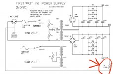
I originally thought I had no understanding of the thermistor wiring in the First Watt power supply circuit diagram I posted.
Then I realized that in fact it does show thermistors wired differently for each primary on the transformer...which was demonstrated by 6L6’s guide.
One is wired to the Line (115-120) on one primary...the other is wired to Neutral (0) on the other primary. There is also a thermistor to ground.
I am just wondering what reason there is for this arrangement.
I have seen other examples of thermistors installed as you have advised in your diagram on just the Line (115-120) primary connections.
We are simply trying to control the sudden large current surge when we power the amp on.
Does it not matter where the thermistors are located?
I am floundering as usual with silly things (wiring and connectors that don’t behave, look horrible or collapse inside of switches when I try to push connectors on)
While I am also having life obligations like getting furnace and cars ready for winter I am thinking about the diagram you posted for me to show how to connect dual primary donuts to the NTC boards for us gringos over on this side of pond.
I spent more time researching and reading about thermistors and how they control in-rush current with high resistance in cold state changing to low resistance once warmed up...also looking at examples in other threads like 6L6’s F5 build guide.
I originally thought I had no understanding of the thermistor wiring in the First Watt power supply circuit diagram I posted.
Then I realized that in fact it does show thermistors wired differently for each primary on the transformer...which was demonstrated by 6L6’s guide.
One is wired to the Line (115-120) on one primary...the other is wired to Neutral (0) on the other primary. There is also a thermistor to ground.
I am just wondering what reason there is for this arrangement.
I have seen other examples of thermistors installed as you have advised in your diagram on just the Line (115-120) primary connections.
We are simply trying to control the sudden large current surge when we power the amp on.
Does it not matter where the thermistors are located?
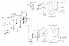
well - just take it this way - NTC and winding are in series ..... it is really irrelevant in which order you are putting them
what I did show in sketch for my NTC pcb is most convenient way to use that one
observe that in Ole Country - I mean - on this side of Pond, in most countries mains plugs are not polarised as they are on your side of Pond..... so even position of switch and fuse ( are they in Phase or Neutral is not strictly declared .......... but (in Eu) that is also calling for dual switches - always best to switch both leads , simply because you never know their orientation
so, just chill
Thank you...I am now chilled.
This is what I thought was going on...my OCD was messing with me.
Still, I would rather have a better understanding of what was going on than to continue blindly marching forward.
This is what I thought was going on...my OCD was messing with me.
Still, I would rather have a better understanding of what was going on than to continue blindly marching forward.
Mr. Chromenuts:
"There is also a thermistor to ground."
Just to confirm: this third thermistor is in the ground path (PS ground to chassis ground) - and not connected to hot or neutral, as illustrated in the FW PS circuit diagram, your post 524.
"There is also a thermistor to ground."
Just to confirm: this third thermistor is in the ground path (PS ground to chassis ground) - and not connected to hot or neutral, as illustrated in the FW PS circuit diagram, your post 524.
@pfdavid
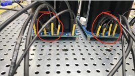
Yes that is how I am interpreting it.
I am using Mighty ZM’s Cap Bank boards.
He has been generous in supplying a convenient neat little way to mount and connect said third thermistor.
See pics
Yes that is how I am interpreting it.
I am using Mighty ZM’s Cap Bank boards.
He has been generous in supplying a convenient neat little way to mount and connect said third thermistor.
See pics
Attachments
I'm planning on using one of Mark Johnson's start-up modules in my SissySIT build.
PCB: low voltage On-Off switch drives AC mains relay \ includes soft start .. H9KPXG
PCB: low voltage On-Off switch drives AC mains relay \ includes soft start .. H9KPXG
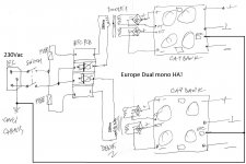
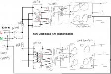
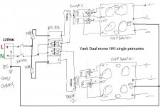
usefull addendum to sketch from post #532
this one for Europe, dual mono
So, fuse not in the same mains pole fo NTC?
I can't see how is that important
fuse will blow if it is in circuit
NTC will do NTC thing if it is in circuit
it is in circuit, be it in front of primary or after
rotate picture by 180deg ........ everything is still going to be the same

fuse will blow if it is in circuit
NTC will do NTC thing if it is in circuit
it is in circuit, be it in front of primary or after
rotate picture by 180deg ........ everything is still going to be the same
I can't see how is that important
fuse will blow if it is in circuit
NTC will do NTC thing if it is in circuit
it is in circuit, be it in front of primary or after
rotate picture by 180deg ........ everything is still going to be the same
One will find a lot of threads about wiring up an amp, with topics about earth/ground as well as mains hot/neutral and fusing.
Problems seem to be that
-protective earth _must_ be its own screw alone, and
-if the fuse happens to be on the neutral, IF it ever blows the chassis still would be… hot? (IIRC all by AndrewT)
-if the fuse happens to be on the neutral, IF it ever blows the chassis still would be… hot? (IIRC all by AndrewT)
Theoretically, yes. And that would happen in most of European countries in about 50% of cases, statistically ...
But: that's what PE to chassis is for ... when the chassis gets "hot", first the internal fuse blows from the current draw. And when the chassis stays "hot" after the internal fuse has blown, it's time for the circuit breaker in your house installation, or the Ground Fault Detector - the last one goes off immediately; for the circuit breaker to trip you will have drawn some current between the "hot" thing in contact with the chassis and the chassis itself ...

HA! wiring
while I'm at the Office
there are also tiny wires for LED thingies, but let ignore them
"chassis" is one M4 bolt (don't forget star washer!!!) near IEC, so all "chassis" leads connected there
while I'm at the Office
there are also tiny wires for LED thingies, but let ignore them
"chassis" is one M4 bolt (don't forget star washer!!!) near IEC, so all "chassis" leads connected there
Attachments
Last edited:
So, fuses on L, NTC on N.
After that at the first amplifier rolling, we involuntary turn the plug on the wall socket and it will be the inverse
After that at the first amplifier rolling, we involuntary turn the plug on the wall socket and it will be the inverse
And instead of a washing machine we got a tumbler/dryer [emoji2955]
Aren’t you using a three-pronged plug?
I usually (haha) lay-out in regards to how installations are usually made, L is right, N left.
Check before running it, adapt if required.
So we keep the washplifier and don‘t accelerate heartbeat.
(As you have guessed already, I am not an electrician…)
Aren’t you using a three-pronged plug?
I usually (haha) lay-out in regards to how installations are usually made, L is right, N left.
Check before running it, adapt if required.
So we keep the washplifier and don‘t accelerate heartbeat.
(As you have guessed already, I am not an electrician…)
😛 as a donut have a phase too this work sweet 😀So, fuses on L, NTC on N.
After that at the first amplifier rolling, we involuntary turn the plug on the wall socket and it will be the inverse
Attachments
And instead of a washing machine we got a tumbler/dryer [emoji2955]
Aren’t you using a three-pronged plug?
I usually (haha) lay-out in regards to how installations are usually made, L is right, N left.
Check before running it, adapt if required.
So we keep the washplifier and don‘t accelerate heartbeat.
(As you have guessed already, I am not an electrician…)
VDE yes, Schuko and Italian plugs are reversible. I use to mark L on cable plugs and sockets
- Home
- Amplifiers
- Pass Labs
- LuDEF