Thanks, Brian. This is, perhaps, what I will want to do with my PC600/600 too 🙂
I made my own PCB to accomodate the adaptors for LU1014 and I made it just for Edcor autoformers - so I was anxiously following your developments...
Learning something new every day. Now I know that even The Mighty ZM can be cheated by some ignorant manufacturer 🙂 so what can we, mere Greedy Boyz, expect in this life 🙂
Fantastic looking amp, Bruce. Congratulations!
Looking forward to building mine. I took the next step a few minutes ago and ordered a few pair of the Cinemags to try out in various amps.
Looking forward to building mine. I took the next step a few minutes ago and ordered a few pair of the Cinemags to try out in various amps.
....
It really is a great sounding AMP!.....
No (enough) porn, no Glory!!
catch22 is that there is never enough Porn

I need to re-do Edcor PC 600:600 pinout on all amps ...... I know ppl are using them less than Cinemagz, at least for my knowledge
Hi ZM
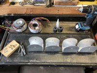
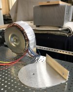
I spent a few free hours this week working on the power supply (between installing new appliances in kitchen and all the other endless renovation details).
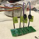
So I made some transformer cradles from scraps of the Pi Metal cases I had to cut out to mount heatsinks...now I can mount them vertically and save some space.
It is still very tight to get extra caps for the supply in that I’d like to have...but I think do-able.
I was reading more about bypass caps in power supplies. Most of what I understand is that it allows a path for AC to ground and filters out high frequency noise.
This seems great...until I read that it works best when the bypass is mounted in the circuit as close as possible to the consumer.
Since I’m struggling with room and I’m not sure how the remotely wired motor runs will benefit me I think I have to pass on them.
It did occur to me to try mounting bypass caps where the power supply connects to the amp boards near the side of the case. I’m not sure if that’s a good idea or not?
I am working from the line voltage end of my supply on through and trying to make sure I’m doing things correctly.
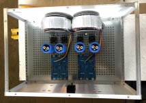
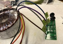
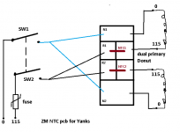
I wanted to ask if you could confirm I am using your NTC boards correctly if I wired them to the primaries on my transformers as I have them in the picture below?
You have said previously that on this side of the pond we would have to use two NTC boards for a dual/mono supply...one per donut.
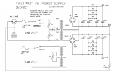
I am using the First Watt F6 Mono supply diagram you have recommended as a model.
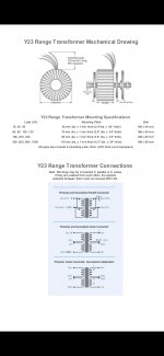
I have labeled the dual primary wiring “0” and “115” for neutral and hot as the manufacturer has designated in the diagram I copied from their data sheet and attached.
My neutral and hot line voltage would go through the fuses in the Schurter inlet module I am using and then be split off of its switch output terminals and connected to the “0” and “115” sections of the NTC board respectively.
I spent a few free hours this week working on the power supply (between installing new appliances in kitchen and all the other endless renovation details).
So I made some transformer cradles from scraps of the Pi Metal cases I had to cut out to mount heatsinks...now I can mount them vertically and save some space.
It is still very tight to get extra caps for the supply in that I’d like to have...but I think do-able.
I was reading more about bypass caps in power supplies. Most of what I understand is that it allows a path for AC to ground and filters out high frequency noise.
This seems great...until I read that it works best when the bypass is mounted in the circuit as close as possible to the consumer.
Since I’m struggling with room and I’m not sure how the remotely wired motor runs will benefit me I think I have to pass on them.
It did occur to me to try mounting bypass caps where the power supply connects to the amp boards near the side of the case. I’m not sure if that’s a good idea or not?
I am working from the line voltage end of my supply on through and trying to make sure I’m doing things correctly.
I wanted to ask if you could confirm I am using your NTC boards correctly if I wired them to the primaries on my transformers as I have them in the picture below?
You have said previously that on this side of the pond we would have to use two NTC boards for a dual/mono supply...one per donut.
I am using the First Watt F6 Mono supply diagram you have recommended as a model.
I have labeled the dual primary wiring “0” and “115” for neutral and hot as the manufacturer has designated in the diagram I copied from their data sheet and attached.
My neutral and hot line voltage would go through the fuses in the Schurter inlet module I am using and then be split off of its switch output terminals and connected to the “0” and “115” sections of the NTC board respectively.
Attachments
-
 4051A5ED-09BB-4F47-A72C-25F5C21C02EE.jpg1,009.4 KB · Views: 269
 -
 D150C4E9-5E0A-4629-8941-F99EF16CADB4.jpg837.9 KB · Views: 271
 -
 2DA23697-4823-4990-95B3-F9045BD589F9.png147.4 KB · Views: 279
 -
 28776484-066B-4E8A-B2C0-E9F6D5AECF9B.jpg144.3 KB · Views: 266
 -
 726EF621-BB31-4873-835E-5AC7417C57DE.jpg722.3 KB · Views: 161
 -
 08DC2C85-9198-4765-AAC7-21137D5B641B.jpg403.5 KB · Views: 254
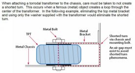
I am concerned that your toroid transformer cradles create shorted turns. My understanding is that the bolt through the middle of a toroidal transformer acts like a secondary winding and the cradles create a short circuit for that additional secondary - the results may not be desirable. I suggest researching the subject before you finalise and power up.
yeah, for starters, solve those cradles; edit: they look heavy enough, you can cut one side and make them L shape
with these you must take bloody care that central bolt is electrically insulated from cradle, or you'll have shortie
see enclosed (origin - from here, Kudos to Author and OP)
NTC pcb dilemma - sketch tomorrow
wiring of bypasses - your logic is proper, I tried as you can see in my builds and tried ditto to pcb - didn't hear difference, so I don't care anymore - doing it in easier way
Attachments
Last edited:
Danger!
Do not power up that amp until you eliminate the shorted turn caused by the mounting bracket and metal bolt. Your transformers will overheat.
The only way to safely use those metal brackets is with nylon bolts passing through the toroids.
Do not power up that amp until you eliminate the shorted turn caused by the mounting bracket and metal bolt. Your transformers will overheat.
The only way to safely use those metal brackets is with nylon bolts passing through the toroids.
Last edited:
Arrrgh...I hate it when I do stupid stuff...brain fart!
I had even seen that information before and read it!
When I searched for vertical toroid mounting options there weren’t many.
There were pricey periphery band style...which were too complicated to make.
I saw a lot of “L” shaped brakets, but it didn’t register.
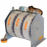
I saw one multi toroid unit pictured below and figured it would be best to have more support since the metal is only 1/16” aluminum.
Anyway, thanks for saving me from a huge bungle!
I think I can pull off the “L” shape.
I was contemplating nylon/plastic bushings for the bolt...but Its probably easier and safer to just hack one leg off.
I had even seen that information before and read it!
When I searched for vertical toroid mounting options there weren’t many.
There were pricey periphery band style...which were too complicated to make.
I saw a lot of “L” shaped brakets, but it didn’t register.
I saw one multi toroid unit pictured below and figured it would be best to have more support since the metal is only 1/16” aluminum.
Anyway, thanks for saving me from a huge bungle!
I think I can pull off the “L” shape.
I was contemplating nylon/plastic bushings for the bolt...but Its probably easier and safer to just hack one leg off.
Attachments
Avel Lindberg torroids are Fabrique en Chine 😱
Did read somewhere that Europe is China's Largest market.
Did read somewhere that Europe is China's Largest market.
......
You have said previously that on this side of the pond we would have to use two NTC boards for a dual/mono supply...one per donut.......
....
NTC pcb dilemma - sketch tomorrow......
Attachments
Thank you for your quick response and sketch Mighty ZM
It isn’t at all how I was interpreting the F6 PS diagram...I’m glad I asked!
Donuts are remounted...except some shielding I want to add.
Looking forward to making more progress.
It isn’t at all how I was interpreting the F6 PS diagram...I’m glad I asked!
Donuts are remounted...except some shielding I want to add.
Looking forward to making more progress.
FWIW, when I was getting my head around shorted turns I noticed a non-metalic bolt in a picture here. Then found on eBay the replacement nylon nuts and bolts sold to anchor toilet seats. 🙂
I have one transformer with a larger nut already epoxied in place, which needs a different solution, but so far so good with all the others. Heat doesn't seem to be a problem but I will check further down the road.
I have one transformer with a larger nut already epoxied in place, which needs a different solution, but so far so good with all the others. Heat doesn't seem to be a problem but I will check further down the road.
Fugly amp ZM. But should call it LuDicrous.
Notice I now have proper Greedy Boy avatar. Moar VFET!! MOAR!!!!
Notice I now have proper Greedy Boy avatar. Moar VFET!! MOAR!!!!
well, me thinks that these amps are iznogood..... most of these devices made for elevators and such, nasty capacitances etc.

well, me thinks that these amps are iznogood..... most of these devices made for elevators and such, nasty capacitances etc.
No, no, no! They are definitely izgroojvy. I see the lightbulb in my head now.
- Home
- Amplifiers
- Pass Labs
- LuDEF