What’s the total dissipation of M102/3+J107?
you got me there, so I've put edit in post #1:
PSU is regular FW Format;
my iteration of same is - per channel - 250 to 300VA Donut with dual 18Vac secondaries, two Graetz bridges, filter bank 33mF-0R1/5W-33mF, per rail
Iq info is given on schmtc - 1A5
so, that would be - effective 22V5dc rails, Iq 1A5, means 67.5W of heat per channel
of that, lower mosfet is having half, LU is having Iq x 2V4= 3W6, cascode mosfet is having (22V5-2V4)x 1A5=30.15W
Thanks. I think I may have found the main issue - minor mistake on the breadboard.
and - you got it behave?
Yes - my application is slightly different since I am using an active front end instead of the transformer, but I got it to stabilize despite this extra complication.
Last edited:
if that is in case (I'm just guessing) - that's simple transition, from AC coupled to DC coupled
cheat, as all Masters are doing**
appropriate high value of series resistor for DC duty- to keep things calm in DC domain, cap in parallel to keep things flat in AC domain
**there are so many hilarious details to dig, in many fine schematics from them; I'm regularly laughing while studying work of Pa, Tim deP. , Allen Wright
Attachments
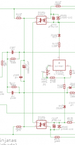
Only 1uF to drive the gate of IRFPs? In the schema of post 1 there is 10uF
........ and 1uF as bypass ......
that's rude, now you're counting my microFahrads......
bypass of 100K resistor?
then no need of low impedance buffer to drive the edcor ?
maybe I will better understand if you post the full schema of post 105
then no need of low impedance buffer to drive the edcor ?
maybe I will better understand if you post the full schema of post 105
Only 1uF to drive the gate of IRFPs? In the schema of post 1 there is 10uF
bypass of 100K resistor?
then no need of low impedance buffer to drive the edcor ?
maybe I will better understand if you post the full schema of post 105
you'll wait little more to see that schematic ( need to do more testing)
point is - these caps are having nothing with autoformer ( when it's there, it is left from gates, being connected through 10uF Silmic, as Papa is doing it
schematic part I posted is for active FE instead of xformer and , again, value of these caps is having nothing with FE itself
said caps - their value ( being one Silmic, or two as drawn on that partial schm)- are completely in function of Rin of OS itself, which roughly but practically close to two rail resistors in parallel
in my previous sketches these being R+ and R-
so, you can say that practical Rin of OS is in range of 20-23K5, more or less
now, by simple calculus F=1/(2 x Pi x R x C) , it is clear that 10uF Silmic is way too big for said Rin, but why not - it is small, nice sonic character in these amps, especially when bypassed with my fave 1uF MKC
in iteration with active FE, I need DC connection between FE and OS, to allow servo function of FE itself while not spoiling impedances in biasing circuit, thus I chose that visible arrangement of resistors and caps ....... with values big enough for purpose
anyway, that's scope for some future thread, when it's done and sealed
Hi Zen Mod,
After Lu1014D + IRFP240 cascode, will the unique property of Lu1014D (SIT similar curve at low Vds and low Ids) get lost?
I had a discussion with one of my SIT enemy. He insists Lu1014 behaves not like SIT anymore.
After Lu1014D + IRFP240 cascode, will the unique property of Lu1014D (SIT similar curve at low Vds and low Ids) get lost?
I had a discussion with one of my SIT enemy. He insists Lu1014 behaves not like SIT anymore.
if you re-read Papa's articles, regarding ZV8, ZV9, F3 .......... cascoding is the way to get exactly that triodish transfer characteristic
so, you can say to your SIT enemy to go fishing, or making Bonsai or whatever
I'm personally trying to not comment things about which I'm ignorant
that's proper way of being just ignorant, maybe learning some , but certainly avoiding to be plain stupid
so, you can say to your SIT enemy to go fishing, or making Bonsai or whatever
I'm personally trying to not comment things about which I'm ignorant
that's proper way of being just ignorant, maybe learning some , but certainly avoiding to be plain stupid
then ask him - what solution is better (than cascode) to obtain that "low Vds" ?
observe curves and see that current span is much broader and not critical, as voltage span is....
without cascode, only solution is so low rail, that probably only headphone amp is possible
so, it seems that in his knowledge, cascoding is obviously something different
anyway, show him schm and say that here in Papaland we are not using cascodes, we are using Voltage Umbrellas (all sorts, floating, not floating, modulated, nonmodulated, folded and nonfolded , blue, red, green ....... )
Might be more helpful to just say LU is a Jfet part, not an SIT part. Has its own character, at low cascoded voltage. I've heard it, genuine F3 even. Didn't sound like another mosfet, in fact I enjoyed it very much. Go for it.
triode is triode is triode ...... be it glass or sand, whichever type of sand
and triode doesn't care how you call it, its just doing its triodish things
ok, time for nap 🙂
and triode doesn't care how you call it, its just doing its triodish things
ok, time for nap 🙂
triode is triode is triode ...... be it glass or sand, whichever type of sand
and triode doesn't care how you call it, its just doing its triodish things
ok, time for nap 🙂
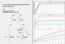
I am trying to understand the "triode" character of the cascoded LU JFET. Vds is held constant via the cascoding, so any triode behavior that the JFET might have had is made to disappear. Below is a simulation, showing the LU1014 JFET with and without cascoding. The curves in the lower plots show drain current vs. Vds for 3 difference values of Vgs. The uppermost plot shows Vds across the cascoded JFET.
What am I missing about the triode behavior of the LuDEF?
Attachments
frankly, I didn't go that much in analysis of LU triode character, simply not being interested in that, being interested in final result
Pa gave his view of LU behavior in ZV8, ZV9 and F3 related writings, and given recipe (mainly Vds) I took directly from there
Was stubborn to pursue Square Law (dubious for triodes, especially for dubious triodes..... or exactly applicable for dubious triodes )
anyway to cut story short, from my musings and fun with real Tube triodes , I know few things:
-I like them cascoded, both soft and hard
-I don't like them in Mu Follower
-I don't like them in White Follower
-etc.
does real tube triode still have pure triodish character when cascoded?
naah, but that way I made tube stages not sounding as Average Joe's tube stage - softie and lalala ...... plenty of not-average-joes around and better to take their constructions in consideration what's proper
same logic applied to LuDEF, especially easy when recipe was there
though, I'll follow with interest what you're going to find, more learning for me 🙂
Pa gave his view of LU behavior in ZV8, ZV9 and F3 related writings, and given recipe (mainly Vds) I took directly from there
Was stubborn to pursue Square Law (dubious for triodes, especially for dubious triodes..... or exactly applicable for dubious triodes
) anyway to cut story short, from my musings and fun with real Tube triodes , I know few things:
-I like them cascoded, both soft and hard
-I don't like them in Mu Follower
-I don't like them in White Follower
-etc.
does real tube triode still have pure triodish character when cascoded?
naah, but that way I made tube stages not sounding as Average Joe's tube stage - softie and lalala ...... plenty of not-average-joes around and better to take their constructions in consideration what's proper
same logic applied to LuDEF, especially easy when recipe was there
though, I'll follow with interest what you're going to find, more learning for me 🙂
- Home
- Amplifiers
- Pass Labs
- LuDEF