About cascoding.
This will only be possible for the lower LU1014D ... or ... ???
This will only be possible for the lower LU1014D ... or ... ???
You will lose some voltage headroom.
So you probably need to raise rail voltage to cover the extra voltage needed for the cascode.
(i.e. not possible with 12V rails)
Other than that, nothing really wrong, IMHO. Actually improves linearity.
Just a bit more complex. And complexity does not cost anything in Spice.
🤓
Patrick
Found the adapters files😉Gerber files for the LU1014D Adapter PCB-
Make sure to select- 2W/(m K) insulator for the aluminum board. Keep in mind not all PCB fab houses offer the 2W/(m K) option.
Attachments
I think you are a bit pessemistic.ZVP3310A is in short supply, TP2104N (from microchip) is readily available.
ZVP3310A transconductance 14.9mA/V, Rds 13.7 Ohm, Vgs(off) 2.00V @5uA, Vgs(on) 3.39V@5mA
TP2104N transconductance 27.5mA/V, Rds 3.7 Ohm, Vgs(off) 1.09V @5uA, Vgs(on) 1.675V@5mA
Plenty of ZVP3310FTA around. But this is of course SOT-23.
Not so many ZVP3310A. The TO-92. It is shortage.
There is no SPICE model of TP2104 around.
But according to datasheet TP2104 turns on at the 1V Vgs level. Or a bit over this.
I have model for TP2640. It turns on giving 3mA at 1.16Vgs.
The ZVP3310A model gives 3mA at 2.25 Vgs.
An option is to use a BJT PNP transistor in the place of ZVP3310A. Such as 2N5401 or alike.
With the B-E Voltage like 0.65 for 3mA.


24V rails, cascoded LU1014 as in ZV9, 26dB gain.
I'll leave those interested to play with the Spice files and optimise further.
As mentioned before, THD vs Amp., THD vs. Freq., Open Loop Gain & Phase, ...., etc.
But it will never be the same in real life.
So the truth will still be told with real hardware.
We have been working in the past years on something totally different with the cascoded 1014s, in real hardware.
The simulation was done in weeks, but the real experimental work is taking MUCH longer.
Cheers,
Patrick
.
Attachments
Can you show some plots?As mentioned before, THD vs Amp., THD vs. Freq., Open Loop Gain & Phase, ...., etc.
Not everyone has SPICE, or knows how to use SPICE, or agrees with "learn SPICE, it's good for you".
There is nothing like a real life build.
SPICE is interesting to play with, as long as you do not believe the data too much.
SPICE is interesting to play with, as long as you do not believe the data too much.
Not everyone has SPICE, or knows how to use SPICE, or agrees with "learn SPICE, it's good for you".
You can always choose to optimise on hardware instead, like any circuit designer would have to do in the end.
Or maybe you can ask Nelson nicely if he would do it and then start a new project ?
🤓
Cheers,
Patrick
There is nothing like a real life build.
SPICE is interesting to play with, as long as you do not believe the data too much.
Does it mean we should not believe in what you publish here, since you never build ?
😀
Patrick
Last edited:
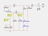
It is an IRFP240 follower. With 2x15VAC transformer input value.
15Vac + bridge rectifier will probably get you 18VDC peak, allowing 3V rectifier drop at peak current, not ?
Then not a bit tight for 16.8V Zeners, allowing also for ripples after rectifiers and caps ?
Did you simulate with AC voltage including internal resistance and inductance of transformer, and real-life rectifiers ?
With 12V 1.4A output, you will be burning 12.5W per rail ?
Patrick
It should be a strong transformer. Maybe 200VA.
18VDC sounds a little at the lower side.
However I may have to change the resistor feeding the zeners ...
18VDC sounds a little at the lower side.
However I may have to change the resistor feeding the zeners ...
The circuit cannot sim without the 2SJ168 model. Can you add that please? It will likely need the other devices as well.24V rails, cascoded LU1014 as in ZV9, 26dB gain.
I'll leave those interested to play with the Spice files and optimise further.
As mentioned before, THD vs Amp., THD vs. Freq., Open Loop Gain & Phase, ...., etc.
But it will never be the same in real life.
So the truth will still be told with real hardware.
We have been working in the past years on something totally different with the cascoded 1014s, in real hardware.
The simulation was done in weeks, but the real experimental work is taking MUCH longer.
Cheers,
Patrick
.
Download available at Toshiba :
https://toshiba.semicon-storage.com/ap-en/semiconductor/product/mosfets/detail.2SJ168.html
Patrick
https://toshiba.semicon-storage.com/ap-en/semiconductor/product/mosfets/detail.2SJ168.html
Patrick
I like the Toshiba k170 much better there…I remember you used ZVP3310 in input of a ZEN variation to achieve higher input impedance.
If I am not mistaken.
Here is one suggestion on Power Supply +/-12.0 Volt.
It looks as it can be good.
Pretty good PSRR - Power Supply Rejection ratio.
You need a good transformer 2x15VAC 150 or 200VA. To be connected both to Left and right channel.
And some Rectifier diodes or diodbridge.
It looks as it can be good.
Pretty good PSRR - Power Supply Rejection ratio.
You need a good transformer 2x15VAC 150 or 200VA. To be connected both to Left and right channel.
And some Rectifier diodes or diodbridge.
Attachments
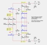
For serious simulation of power supplies, I personally would do the following :
1) Choose a transformer and dig out the spec (e.g. from Toroidy) for the no-load voltage.
This allows one to calculate the internal resistance of the secondary.
Model the transformer secondary as a 50Hz AC voltage source, plus a series resistance.
2) Include rectifier diodes one wants to use, in spice, plus the (not ideal) cap one wants to use.
LT Spice has a wide selection of electrolytic caps with realistic models.
Only then can one see what the peak rectifier currents is, and how much actual voltage drop and remaining ripple one can get after the first bank of caps.
Using IRFP MOSFETs will always mean that you need to drop ~5V because of their high Vgs.
Especially for 12V output voltage, this is very inefficient and expensive (extra VA for the Tx, extra heatsink, .....).
The solution to this "problem" is widely published.
Either you use a Darlington, as in JLH Class A, or a low-Vgs, high-Yfs MOSFET.
Which is why we use 2SK3497 / 2SJ618 in the F5X, with Vgs ~2V.
And of course I know they are obsolete.
So practically only Darlington's left.
Depending on the ripple voltage after the first caps, you will need ~2V drop minimum for the follower to work properly.
Even with Darlington's.
Just my 2 cents from real-life experience,
Patrick
- Home
- Amplifiers
- Pass Labs
- LU1014D Small Amplifier 6 Watt with low distortion