
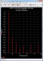
This figure with the Fourier spectrum still has the same issue as before. The y-axis units (V) do not seem to make sense with those numbers (0...-180).
What did you plot on the y axis?
What did you plot on the y axis?
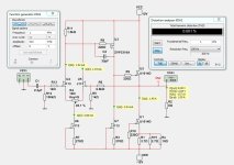
Thermal stability of the circuit? Those small LU are going to be very hot at 15+ Watt dissipation.
I don't know about the thermal of LU1014D.
I have to ask Nelson Pass about this 🙂
The bigger the heatsink is - the better. Of course.
Here is an example 😀
I have to ask Nelson Pass about this 🙂
The bigger the heatsink is - the better. Of course.
Here is an example 😀
Attachments

Last edited:
I never actually build my circuits.
I leave that to others.
Nic,
There is no thermal issues in Spice. 🙂
Patrick
But for a through design, perhaps you care to show some more data points, such as :
Frequency plots for open and close loop gain & phase
Distortion at other power level (e.g. 4W) and at other frequencies (e.g. at 10kHz)
?
Patrick
Frequency plots for open and close loop gain & phase
Distortion at other power level (e.g. 4W) and at other frequencies (e.g. at 10kHz)
?
Patrick
Well then Spice is very far from the real world....There is no thermal issues in Spice. 🙂
And what voltage does 0 dB correspond to? What was the load?It is decibel dB.
For example 2nd harmonic has like -100dB.
It is very little voltage.
The voltage at 1 Watt into 8 Ohm = standard for measuring. This is 4.0 Vpk.
So, it is 4 Volt peak = 0 dB
-100 dB is 0.00004 Volt.
-120 dB is 0.000004 Volt. Same as 4 uV
So, it is 4 Volt peak = 0 dB
-100 dB is 0.00004 Volt.
-120 dB is 0.000004 Volt. Same as 4 uV
From the data sheet the thermal resistance of the LU1014D is 1.8 ºC/W (junction to case).
According to my measurements the LU1014D has a positive tempo of around 15mA/ºC.
Assuming you have a heatsink big enough to limit the temperature rise to say 30ºC above ambient this would mean a rise in die temperature equal to roughly 60ºC (30ºC + 12V*1.4A*1.8ºC).
Now 60ºC * 15mA/ºC = 0.9A so the amp should be biased at around 0.5A at ambient temperature for this to work.
I think the amp would be very, very slow to reach desired bias (safe heatsink size), or in serious risk of thermal runaway (borderline heatsink size).
Maybe some more circuitry is needed?
Not quite.
The bottom LU1014 (U1) has a large source resistor (1.2R)
As Id increases with temperature, the voltage across the source resistor also increases with current.
This reduces the effective Vgs applied to the JFET, thus reducing Id in turn.
So if the source resistor is large enough, the bias can sort of self stabilise.
In this circuit, the bias of the top LU1014 is controlled by the negative feedback loop.
So it will largely follow the bottom JFET, if there is enough NFB.
You can also add an extra bias-stabilising circuit similar to that in the EB602 (around Q4,5) :
https://www.diyaudio.com/community/threads/the-borbely-eb602-200-revisited.325163/

Patrick
The bottom LU1014 (U1) has a large source resistor (1.2R)
As Id increases with temperature, the voltage across the source resistor also increases with current.
This reduces the effective Vgs applied to the JFET, thus reducing Id in turn.
So if the source resistor is large enough, the bias can sort of self stabilise.
In this circuit, the bias of the top LU1014 is controlled by the negative feedback loop.
So it will largely follow the bottom JFET, if there is enough NFB.
You can also add an extra bias-stabilising circuit similar to that in the EB602 (around Q4,5) :
https://www.diyaudio.com/community/threads/the-borbely-eb602-200-revisited.325163/
Patrick
Last edited:
This also means the amp would run out of current before reaching the specified 6W into 8 Ohm.Now 60ºC * 15mA/ºC = 0.9A
What's wrong with cascoding the LUs to relieve them from the heavy lifting?
You will lose some voltage headroom.
So you probably need to raise rail voltage to cover the extra voltage needed for the cascode.
(i.e. not possible with 12V rails)
Other than that, nothing really wrong, IMHO. Actually improves linearity.
Just a bit more complex. And complexity does not cost anything in Spice.
🤓
Patrick
So you probably need to raise rail voltage to cover the extra voltage needed for the cascode.
(i.e. not possible with 12V rails)
Other than that, nothing really wrong, IMHO. Actually improves linearity.
Just a bit more complex. And complexity does not cost anything in Spice.
🤓
Patrick
Last edited:
- Home
- Amplifiers
- Pass Labs
- LU1014D Small Amplifier 6 Watt with low distortion