Hello there,
I'm finalising the wolverine amp working on the PSU's. Ordered the crc psu at pcbway designed by Prasi which is the one without the Lt4320
Is there anyone who can source these boards with the dual die mosfets?...I believe it was @xrk970 who posted it a while back.
thx in advance
willem

I'm finalising the wolverine amp working on the PSU's. Ordered the crc psu at pcbway designed by Prasi which is the one without the Lt4320
Is there anyone who can source these boards with the dual die mosfets?...I believe it was @xrk970 who posted it a while back.
thx in advance
willem

Ordered ENIG finished boards at JLCPCB on a panel of 9 boards. I only need 4 assuming I don't mess up one🙂...If someone needs a pair you can either pick them up with me or only pay for the shipment🙂
reg
willem
reg
willem
Hello Gents,..I know it has been discussed a lot and the topic might be getting oldish. I've pretty much read all the posts. Just wanted to assure these specs. I'm running 2 transformers with each 2 secondaries of 42 VAC . So 4 rectifiers. A while back xrk970 tested these.
Advised in this thread would be Vgs of >2 volt ierecommended between 2.5 and 4 volt. would that potentially cause any problems? I will test it and see what happens but some adice would be helpfull.
Advised in this thread would be Vgs of >2 volt ierecommended between 2.5 and 4 volt. would that potentially cause any problems? I will test it and see what happens but some adice would be helpfull.
SQJQ910EL-T1_GE3
| Number of Channels: | 2 Channel | |
| Vds - Drain-Source Breakdown Voltage: | 100 V | |
| Id - Continuous Drain Current: | 70 A | |
| Rds On - Drain-Source Resistance: | 8.6 mOhms | |
| Vgs - Gate-Source Voltage: | - 20 V, + 20 V | |
| Vgs th - Gate-Source Threshold Voltage: | 2 V | |
| Qg - Gate Charge: | 46 nC |
Do you have SQJQ910EL-T1_GE3 already? Looks like they are out of stock in many places. That might affect your decision.
Not yet.....they ARE out of stock with most supplies but I found some stock at Flywing. Shipment is a bit expensive however.Do you have SQJQ910EL-T1_GE3 already?
https://www.flywing-tech.com/p/5727712
reg
w
A possible alternative is this one. But with 228 AC and unknown fluctuations and 42x1.41= 59 volt to close ofr comfort.
SQJB00EP-T1_GE3
| Number of Channels: | 2 Channel | |
| Vds - Drain-Source Breakdown Voltage: | 60 V | |
| Id - Continuous Drain Current: | 30 A | |
| Rds On - Drain-Source Resistance: | 10.5 mOhms | |
| Vgs - Gate-Source Voltage: | - 20 V, + 20 V | |
| Vgs th - Gate-Source Threshold Voltage: | 2.5 V | |
| Qg - Gate Charge: | 35 nC |
... You're looking to get 60V from these!
likely also limiting yourself on the max value of the MLCC output snubbing cap. For a12V rectifier I found a 16V 47uF cap to be the remedy to the FETs ringing.
Be careful with ultra low Rds On FETs, they will likely ring unless damped. I found the small lytic to be useless in this role.
You'll need to check in circuit with your scope
Hi,Hello Gents,..I know it has been discussed a lot and the topic might be getting oldish. I've pretty much read all the posts. Just wanted to assure these specs. I'm running 2 transformers with each 2 secondaries of 42 VAC . So 4 rectifiers. A while back xrk970 tested these.
Advised in this thread would be Vgs of >2 volt ierecommended between 2.5 and 4 volt. would that potentially cause any problems? I will test it and see what happens but some adice would be helpfull.
SQJQ910EL-T1_GE3
Number of Channels: 2 Channel Vds - Drain-Source Breakdown Voltage: 100 V Id - Continuous Drain Current: 70 A Rds On - Drain-Source Resistance: 8.6 mOhms Vgs - Gate-Source Voltage: - 20 V, + 20 V Vgs th - Gate-Source Threshold Voltage: 2 V Qg - Gate Charge: 46 nC
you can use these mosfets, no problem.
regards
prasi
Hi Willem,
The SQJQ910EL-T1_GE3 is PowerPAK 8 x 8L Dual package size which will not fit the pcb you have.
SQJB00EP-T1_GE3 is the correct package size SO-8L Dual that fits Prasi's pcb.
Unfortunately, its out of stock 😫
An alternative that's in stock is: SQJ974EP-T1_GE3
Rds(on) is a bit higher, but should be ok.
sqj974ep.pdf
I do have the Prasi board for the dual mosfet. Not the one on the forum.
Thing is ... I have 2 transformers with each 2 42vac sexondaries. The voltage the fets need to be able to endure is around 58 volts. Taking into account swings, margin etc... they need to be rate 80 volts minimim
Thing is ... I have 2 transformers with each 2 42vac sexondaries. The voltage the fets need to be able to endure is around 58 volts. Taking into account swings, margin etc... they need to be rate 80 volts minimim
Thx Vunce...
SQJQ980EL-T1_GE3
Vgs 2volt
Qg 26nC
Vds 80 volt
Rds 13 mOhm
max current 36A
IF I understand it correctly this well within spec
reg
willem
This one ins ony 5 mm wide. Bit smallish to solder...i found this one which is at least available.SQJ974EP-T1_GE3
SQJQ980EL-T1_GE3
Vgs 2volt
Qg 26nC
Vds 80 volt
Rds 13 mOhm
max current 36A
IF I understand it correctly this well within spec
reg
willem
The specs are good, but it will not “physically“ fit the pcb you have. The package size is too large.
You need a dual mosfet in “SO-8L” package size.
You need a dual mosfet in “SO-8L” package size.
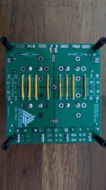
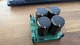
Dear diy'ers.
I am making a CRC power supply- rectifier and smoothing cap combo. Getting back to finish my project after 3 months of side quests 🙂
Can you please have a look if my power supply is soldered correctly?
Thank you.
I am making a CRC power supply- rectifier and smoothing cap combo. Getting back to finish my project after 3 months of side quests 🙂
Can you please have a look if my power supply is soldered correctly?
Thank you.
Attachments
Hey Vox,
You have eliminated the ‘R’ by installing jumpers, you have straight CC psu now. I assume that's what you wanted?
Use the Quasimodo jig and O-scope to measure your trafo secondaries for the AC side snubber components. Don’t forget the 100nF film cap on the DC side.
You have eliminated the ‘R’ by installing jumpers, you have straight CC psu now. I assume that's what you wanted?
Use the Quasimodo jig and O-scope to measure your trafo secondaries for the AC side snubber components. Don’t forget the 100nF film cap on the DC side.
Thanks Vunce. I am just being cautious hence my question on wiring. I won't use snubber, at least not yet.
Re 100 nf cap -thanks, I was not sure if it was needed or not cause I don't fully understand how circuits work yet.
Re 100 nf cap -thanks, I was not sure if it was needed or not cause I don't fully understand how circuits work yet.
- Home
- Group Buys
- LT4320 based active rectifier