
Hi Prassi.
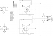
For R9 (output zobel) the schematic shows 1Ω, while the BOM part is 10Ω.
Hello Alazira,
Right-on..
I have it corrected here.
This is an example bom only, one is free to choose whatever components available with him, as pcb is more or less universal with many options for most components.
regards
Prasi
Attachments
Hello all,
Thanks for making payments expediently.
I will start the shipments on monday. 6-8 at a time as the list.
LT4320+CRC PSU GB - Google Sheets
regards
Prasi
Thanks for making payments expediently.
I will start the shipments on monday. 6-8 at a time as the list.
LT4320+CRC PSU GB - Google Sheets
regards
Prasi
Hi Prasi, Looking forward to receiving my boards!
One quick question, I am building an Aleph J psu and it has a 2k2 bleeder resistor in the recommended circuit diagram. Is there provision for this on your boards?
One quick question, I am building an Aleph J psu and it has a 2k2 bleeder resistor in the recommended circuit diagram. Is there provision for this on your boards?
Hi Mpa,
R4 is the bleeder resistor for the PSU. It can use a 2200 ohm and upto 3-5W resistor in that position. Hope this is the info you are looking for.
Regards
Prasi.
R4 is the bleeder resistor for the PSU. It can use a 2200 ohm and upto 3-5W resistor in that position. Hope this is the info you are looking for.
Regards
Prasi.
Hello Mpa,
Just some thoughts that could help optimize the psu. The BoM is just a suggestive one.
1.You may want to increase the capacitance of the Main filter caps depending upon your amplifier and parts available with you.
2. Another aspect is Transformer snubbers (CS,CX, RS), you may have to find the correct values depending upon your transformer based on quasimodo design by Mark Johnson or leave them out completely.
3. R of CRC will depend upon your choice, anything from 0.1 to 0.33 ohm can be used here depending upon loss of voltage you can tolerate vs the ripple reduction.
4. LED resistor and power needs to selected based on your voltage.
I have tried to make the BoM as informative as possible including maximum dimensions and pitch spacings of components that PCB can take.
So, request everyone to spend some time studying their amplifier requirements and how best to customize this particular PSU to fulfill those requirements.
regards
Prasi
Thanks Prasi. I have snubber values for my transformer from the quasimodo results thread. Would those still be valid for this circuit? Also, am I best to stick to the R values of CRC from the original Aleph J psu design? 0.47r 3W I think.
In both cases, yes. It makes perfect sense to stick to those values. You could increase the power rating of resistos to keep them cool..
e. g. 1 ohm -5W in parallel.
It will run cooler and longer
e. g. 1 ohm -5W in parallel.
It will run cooler and longer
Last edited:
oh, in that case, it should be 0.25R-5W parallel...
Or one could also use the 10W vishay LVR and piggy-back them for 20W .
vishay lvr Vishay LVR Series 10 W Wirewound Resistors - Through Hole | Mouser India
OR use the caddock part and mount it on bottom plate / heatsink.
MP821-0.10-1% Caddock | Mouser India
Or one could also use the 10W vishay LVR and piggy-back them for 20W .
vishay lvr Vishay LVR Series 10 W Wirewound Resistors - Through Hole | Mouser India
OR use the caddock part and mount it on bottom plate / heatsink.
MP821-0.10-1% Caddock | Mouser India
That Caddock resistor looks great. So I would need 0.1 ohm 20w and mount it on a heatsink?
Thanks for the advice guys!
Thanks for the advice guys!
That Caddock resistor looks great. So I would need 0.1 ohm 20w and mount it on a heatsink?
Thanks for the advice guys!
In free air the 821 is rated at 2.25W so for aleph will need a small heatsink or mounted to your chassie.
something like this 10PCS TO-220 Silver Heatsink Heat Sink for Voltage Regulator or MOSFET NEW K9 733180817815 | eBay
Hello guys,
there was a mistake in bom with regard to resistor value of CRC. I had selected 20mOhm, 30mOhm.
these have now been corrected to 220mOhm, 330mOhm , etc.
regards
Prasi
Thanks Prasi.
- Home
- Group Buys
- LT4320 based active rectifier