If using a scope you can also observe the frequency of the ripple. 50Hz confirms half wave rectification.
The circuit which treats each transformer winding separately and adds the outputs is the only way to achieve a full wave rectified symmetrical PS.
The half wave rectification is not to be ignored. I have always preferred its sound using Si or Ge diodes and seem to prefer it with the 4320 as well.
Provided there is ample capacitance to make up for the ripple and the positive and negative current draws are roughly the same to avoid imbalanced dc currents through the transformer, there is no reason not to try it.
Btw Tibi's new GB for 1170 based sync rectifiers is free of the 4320 limitations. It also works with standard centre-tapped transformers and a single board is sufficient for full wave, symmetrical power. And for less than half the cost.
Hello AV,
yes correct.
here is the scheme by Tvicol (tibi) on how to build dual bridge full wave rectifier with dual secondary transformer.
https://evotronix.eu/main/wp-content/uploads/2020/03/SalignyALL@2x.png
yes correct.
here is the scheme by Tvicol (tibi) on how to build dual bridge full wave rectifier with dual secondary transformer.
https://evotronix.eu/main/wp-content/uploads/2020/03/SalignyALL@2x.png
All these circuits boil down to positive supplies, some of them connected in series. If one forgets about transformers ending with 3 wires all is then well. Or surgically convert the 3 wires to 4, easy with toroids.
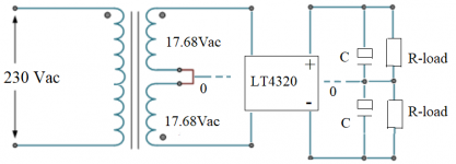
The measurement will be done twice, each on a different newly soldered active rectifier. The active rectifier is wired for dual supply as summerized in post 855. Measured by two different voltmeters, and a scope with AC in: 2 x 17.68V. After the capacitance and resistor is added the result will be reported.
Last edited:
I'm a bit lost with that post 855 on how you've set up the active bridge with this is phase, out of phase connections.
As I understand, you've used each single winding of the transformer to feed each LT bridge, yes, and you're getting wildly different results, yes but what current are you passing thru what load after smoothing with what capacitor/resistor?
And, have you joined the 2 supplies, after the bridges to get your + & - rails?
As there appears to be no schematic of my setup in this thread, herewith you will find my sketch (sorry, don't have the proper software at hand now). The capacitance will be 2 x 10.000uF per side, the second capacitor is selectable to see the effect. The first test load will be set for about 100mA.
Attachments
Hmm! Try it with a 16R load and give the fets something to do - put the resistors (R-load) in water if get too hot
Herewith some pictures to illustrate some of the loads I use for various purposes. Yes, including 2 x 8 ohm in rather high wattage (see on the photo the ball point for comparison of the size).
My first aim is to apply the LT4320 as a dual supply for a line amp requiring about 100 mA. So, instead of putting a heavy load on the mosfets (currently IPP072N10N), I prefer to invite suggestions for mosfets that feel comfortable with a light load, and would fit the LT4320 requirements. Are there any?
Also a picture of the rectifier unit with 2 x 10.000uF to be used for the test. Prasi may recognize the board. Of course, for the test of the LT4320 the rectifiers on the board will be bypassed.
Last edited:
I've been following this thread for a while, since I am on the list for some of prasi's boards. I am baffled by the whole discussion around in-phase trafo windings, half-wave rectifiers, etc.
If your goal is to produce dual voltage outputs with low ripple, why not just use the dual windings as intended and separate full-wave rectifiers - more parts of course, but this is well established best practice.
Using a single bridge with a center tapped trafo (which is by nature out of phase) is less efficient. And I am fairly certain that using ideal rectifiers in half wave configurations defeats the idea behind them.
Am I missing some obscure design goal here?
1. Most off the shelf centre tapped transformers do not have dual windings. It is relatively easy to do a conversion on a toroidal, but not so on an EI
2. Surprisingly, some of us just are cheapskates 😀
2. Surprisingly, some of us just are cheapskates 😀
3. From an audible perspective - as raised already by analog_sa in post 861 - it may be interesting to opt for a half wave rectification. I intend to compare half wave and full wave rectification with the LT4320 design. Over-thinking, and over-listening; oh well.
A prerequisite is to have no hum in either setup, which appears to require quite some capacitance for the half wave setup. That is how I got into my quest here.
At the moment the test is at 20.000uF on 2 x 75 ohm load (almost 300mA). A 50Hz ripple of 220mV TT on both positive an negative. With a resistor of 0.47 ohm between the two 10.000uF capacitors the ripple is with 150mV again somewhat lower. When then connecting a standard regulator - an extra 2.200uF and LM7815 / LM7915 - this results in no hum on the scope, just about a mV 'generic' noise. Finally. The negative supply still remains somewhat restless, though. Full report to come.
Last edited:
Hello All,
lockdown in my city just got extended by another 15 days😡.
Sorry for the inordinate delay.😱 . I dont know what to say but thanks for hanging in there patiently.
regards
prasi
Hi prasi - any updates on the lockdown affecting shipment to US?
Thanks!
Hi wtnh,
Still the international shipping from India hasn't started to any of the countries. Its very frustrating, but cant do anything to change the situation.
regards
prasi
Still the international shipping from India hasn't started to any of the countries. Its very frustrating, but cant do anything to change the situation.
regards
prasi
I'll send a pigeon. Please feed it as it's a long way back.😀
Could we do a group buy for the pigeon? 😀
Hi wtnh,
Still the international shipping from India hasn't started to any of the countries. Its very frustrating, but cant do anything to change the situation.
regards
prasi
Prasi,
it's not your fault and for a good thing it is worth waiting.
Best regards
Guenter
Hi Harry,
yes, its too high.
The following is better suited and slightly cheaper too.
https://www.mouser.in/datasheet/2/427/sup70060e-1764703.pdf
Vds-100V
Rdson-5.8mOhm
Vgsth-2-4V
Qg-53.5nC
price-18USD for 10 nos.
stock qty : 538 in stock.
Prasi, getting mouser items now in India is becoming difficult and expensive so the only saving grace is rsdelivers. I find this and the other ones are out of stock but I could only find this one - https://in.rsdelivers.com/product/v...nel-mosfet-120-a-100-v-3-pin-to-220ab/1242249
Is this a good replacement for this power mosfet? Do you suggest any other good ones which we can get locally within India online sites as using element14 is difficult for retail customers.
Thanks
- Home
- Group Buys
- LT4320 based active rectifier