Hi Prasi,
I would like 6 pairs of THT rectifier, 4 pairs of the SMD, and 4 of the power supply PCB's Thanks! I will PM my information.
Steve.
I would like 6 pairs of THT rectifier, 4 pairs of the SMD, and 4 of the power supply PCB's Thanks! I will PM my information.
Steve.
pl check latest status on google sheets here
GB-2, LT4320 RECTIFER PCBS AND LT4320-CRC PSU PCBS - Google Sheets
GB-2, LT4320 RECTIFER PCBS AND LT4320-CRC PSU PCBS - Google Sheets
Prasi,
I received my two C-R-C + 4320 boards. They appear to be very solid.
I don't find myself on the Google sheet.
Thanks,
Ron
I received my two C-R-C + 4320 boards. They appear to be very solid.
I don't find myself on the Google sheet.
Thanks,
Ron
Prasi,
I received my two C-R-C + 4320 boards. They appear to be very solid.
I don't find myself on the Google sheet.
Thanks,
Ron
Hello rinman,
thanks for confirmation. You were on GB no.-1 list for the crc+lt4320 pcbs.
LT4320+CRC PSU GB - Google Sheets
I am currently doing GB no. 2
GB-2, LT4320 RECTIFER PCBS AND LT4320-CRC PSU PCBS - Google Sheets
regards
Prasi
That does not tell the whole story.
I have built two amplifiers with LT4320 based rectifiers, and they both exhibit a significant amount of voltage drop beyond a simple RdsOn * quiescent current. In the case of my M2x, the transformer is delivering its rated secondary voltage of 18V RMS to the input of the rectifier. Peak sinusoidal amplitude is 18 * 1.4 = 25.2 Volts. The CRC filter drops 154 mV, leaving about 1.64V as the remainder which is consumed by the LT4320 based rectifier. This is not bad, and is a worthwhile improvement over conventional diode bridges, but certainly isn't the 'ideal' either.
The SLB power supplies that I'm using in my hotrod F6 exhibit similar performance in their rectifier and CRC sections. When I was making voltage measurements using an earlier quiescent current of 1.45 Amps and Antek AS-3222 transformers which were delivering 22V to the inputs of the PSU boards, I was seeing about 28 Volts at the input of the Cap Multiplier section. Good, but still not 'ideal'. The math is very straightforward.
I have been using the IPP029N06N Mosfets in my synchronous rectifiers. These are qualified for the target application and have Rds(ON) and gate charge Qg figures of merit that suggest good performance. It is certainly possible that other Mosfets may have better performance in this particular application, yielding higher output voltage from the rectifier. It would be interesting to hear experiences from other builders who may be using different parts and getting different results.
I'm trying to figure out how you got so much voltage drop on your IPP029N06N FETs unless the Ids current is *really* high. The LT4320 regulation loop sets the gate drive on the FET to set Vds to 20 mV. It can typically put out 7 or 8 V of Vgs which should be plenty to get the IPP029N06N fully enhanced.
It seems like you're getting more like a diode drop - is it possible the FET drain and source are reversed and you're seeing the body diode?
Another possible issue is that you could have a leakage on the gate due to solder flux remnant. The charge pump in the LT4320 can put out a few hundred uA so it would have to be pretty dirty?
What Vgs do you see when the FET goes forward biased?
tommost
Hi Prasi,
Received my package yesterday for the dual supply. Left India around Nov.21st, takes awhile to get here. Thanks for the effort you put in for this GB.
MM
Received my package yesterday for the dual supply. Left India around Nov.21st, takes awhile to get here. Thanks for the effort you put in for this GB.
MM
Just got mine as well, thanks.
Suggestion, get a brown paper roll at office place (they're like 18 inches or something, not the massive ones) and cut it into a few sizes. It's easy to roll up some PCB's in. The packaging seemed like you had to spend way too much time on it.
Suggestion, get a brown paper roll at office place (they're like 18 inches or something, not the massive ones) and cut it into a few sizes. It's easy to roll up some PCB's in. The packaging seemed like you had to spend way too much time on it.
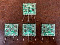
I'm not sure if anyone else has built and tested their LT4320 ideal bridges yet. I assembled a set last night and ran into a lot of problems with the small VSON10 based package. I have built many other LT4320 bridges in the past and have pretty good SMT soldering, and never ran into problems like this before. 3 of the units tested out and work. The 4th exploded one of the MOSFETs with a pop and spark and smoke upon power up with a 250VA 25vac trafo input. I replaced the MOSFET and it still exploded. I re-installed the LT4310 but still explodes MOSFETs, I assume it was killed and osicllates or something upon turn on so instantly destroys the MOSFETs - they become shorted out. In looking at it, I think it may be that these boards were not finished in ENIG and the HASL is kind of rough. It causes maybe small misalignments/shorts or cold solder joints on the tiny underside pads. So perhaps these should be used with the 12 pin MSOP or the DIP pacakge only, not the VSON10 which requires a very precise smooth surface to attach to.
Here are my 4 units with the bad one marked by X. I ended up toasting 4 MOSFETs and 2 LT4320's trying to debug it. Will just toss it and start new.

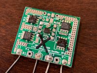
Here is the problem one:

Otherwise, they work well - just avoid the little VSON chips.
Here are my 4 units with the bad one marked by X. I ended up toasting 4 MOSFETs and 2 LT4320's trying to debug it. Will just toss it and start new.
Here is the problem one:
Otherwise, they work well - just avoid the little VSON chips.
Attachments
Yeah, the SMD version of the LT4320 is really tiny. I wouldn't attempt to solder that unless I had a good binocular microscope and a special tip for my soldering station. Maybe a hot air tool as well.
I have successfully built several sets of through-hole boards, including a pair of SLBs as well as simple synchronous rectifiers. I'm saving the SMD boards pictured above for eventually replacing the LVB2650 bridge rectifiers in my Aleph J. The LT4320 will be the 8-pin DIP version.
I have successfully built several sets of through-hole boards, including a pair of SLBs as well as simple synchronous rectifiers. I'm saving the SMD boards pictured above for eventually replacing the LVB2650 bridge rectifiers in my Aleph J. The LT4320 will be the 8-pin DIP version.
Thanks 'X' for finding and posting up this potential problem - really good to know about.
I'm with TA in that the tiny SMD chips are quite daunting and I looked around to find one of those SMD <-> 8 pin convertor boards and/or someone skilled at SMD assembly but haven't found one yet
I've used pcb sockets on the different pcbs (Prasi single fet, Prasi dual fet and SLB) with just the 8 pin chips - so far, so good
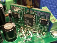
Like in the photo above, I've used the solid copper wire and bent the long legs (with insulating sleeves) to replace the 'normal' diode bridge rectifiers (not the SLB) - the Salas L-Adapter board wasn't so easy but it works very well too.
I'm with TA in that the tiny SMD chips are quite daunting and I looked around to find one of those SMD <-> 8 pin convertor boards and/or someone skilled at SMD assembly but haven't found one yet
I've used pcb sockets on the different pcbs (Prasi single fet, Prasi dual fet and SLB) with just the 8 pin chips - so far, so good
Like in the photo above, I've used the solid copper wire and bent the long legs (with insulating sleeves) to replace the 'normal' diode bridge rectifiers (not the SLB) - the Salas L-Adapter board wasn't so easy but it works very well too.
I actually have hot plate and hot air gun and have successfully soldered VSON chips before successfully. But always on nice smooth ENIG finish boards. The MOSFETs are no problem, but these bottom facing tiny pads really require a smooth surface. The MSOP12 version is not too hard to solder for SMT. Really no reason to use this one unless you are trying to really make it tiny.
I also recently built one of the smd board versions, but cheated and used the LT4320 DIP8 package. It’s replacing the standard diodes on an AMB Sigma11 psu. With a bit of creative positioning it fits perfectly!!
Attachments

- Home
- Group Buys
- LT4320 based active rectifier