I can't thankyou enough for all this help. Indeed I used the 10 watt tap of primary with a small 4 inch 8 ohm fullrange speaker on the secondary. It has got no crossover.
The 6j1 filament are powered by separate trafo of 12 volt,and I used two 6j1 filament in series.
I will try to modify the cathode resistor and give a update. Do you also recommend reducing the cathode resistor on PL504 too?
The 6j1 filament are powered by separate trafo of 12 volt,and I used two 6j1 filament in series.
I will try to modify the cathode resistor and give a update. Do you also recommend reducing the cathode resistor on PL504 too?
I also need to mention that I didn't use 100k pot at the input. Instead, I hooked up directly to a mobile phone headphone out.
Using the mobile phone headset output is okee. Regarding the cathode resistor of the PL504. Schematics of low power PL504 amplifiers on internet show cathode resistors of 39 to 100 Ohm. You could give that a try.
Best is however to start measuring the different voltages in the amplifier, so you can determine what is happening.
Things to measure are:
AC voltages:
the filaments of each tube.
DC voltages:
power supply
on top of anode and G2 resistor of 6J1
anode 6J1
G2 of 6J1
cathode of 6J1
anode of PL504
G2 pin of PL504
cathode of PL504
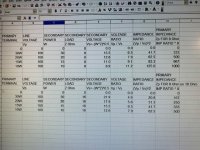
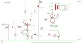
All components as per version 2 schematic.
Voltages measured
Pl504 31 VAC ( both tubes)
6j1 filament DC 5.7 VOLTS
DC VOLTAGES.
PS -84 VOLT
AFTER 2.2K, AT 270K/220K JUNCTION- 83
G2 6J1 50 V
ANODE 6J1 22.3 V
CATHODE OF 6J1 1.8 V
PL504 ANODE 82 VOLT
G2 PL504 82 VOLT
CATHODE OF PL504 - 9.1 V
After reducing the cathode resistor of 6j1 to 4.7k, I noticed a little reduction in the distortion. With a mobile phone as source,the sound is okay with low volumes. As I increase the volume on the mobile,it distorts like clipping. The bass is very low, but mids and highs are excellent.
I use a 0 -24 trafo, with a voltage doubler. I suspect some irregularities in the trafo, since the ac measures 31 VAC and after voltage doubler, it measures 82 volt DC
The higher voltage from the voltage doubler is no problem. The only issue is your safety. You have to take care not to get a shock. Lets first look at the filament supply of the PL504's. You run them in parallel on 31 VAC. This means; 31V - 27 = 4V too much at 0.6 Amp, which means you need a resistor of 6.7 Ohm. I guess a series of a 5 Ohm resistor (4-5 Watt) and a 1.5 Ohm resistor (3-4 Watt) will do the job.
Don't forget that tube pin numbering - seen on the underside - starts with pin 1 on the left of the open space and then clockwise. This is not always obvious from tube data sheets. Sometimes tube sockets have numbers near the pins, but not always. The "A" in in the tube schematic of the PL504 is the top cap.
Thanks for the suggestion. I took precautions and checked pin orientation carefully. I double checked the wiring and component values too. Please let me know how to reduce the audible distortion. Can I reduce the cathode resistor on 6J1 even more? Are my voltage readings within specifications? Since I get the distortion only on increasing the volume. So,will reducing the 6j1 gain will be of help?
Ok. So I now found out the problem sort of. I tried a power trafo,rated 220 primary to 0-24 secondary. The sound output improved a lot,with even noticeable bass. So,I think the design works quite good. Any more improvements I can make?
I'm busy building one channel of this schematic to check what is happening. Should be ready by tonight, if my othger duties allow so. Have you already taken all the voltages?
All components as per version 2 schematic.
Voltages measured
Pl504 31 VAC ( both tubes)
6j1 filament DC 5.7 VOLTS
DC VOLTAGES.
PS -84 VOLT
AFTER 2.2K, AT 270K/220K JUNCTION- 83
G2 6J1 50 V
ANODE 6J1 22.3 V
CATHODE OF 6J1 1.8 V
PL504 ANODE 82 VOLT
G2 PL504 82 VOLT
CATHODE OF PL504 - 9.1 V
After reducing the cathode resistor of 6j1 to 4.7k, I noticed a little reduction in the distortion. With a mobile phone as source,the sound is okay with low volumes. As I increase the volume on the mobile,it distorts like clipping. The bass is very low, but mids and highs are excellent.
I have noted the following voltages. Anything more to be measured?The pin orientation are verified as you suggested
If you fill in the voltages at the appropriate places in the schematic, you can quickly calculate the current flowing through the tubes. Use Ohms law V = I x R. So voltage drop over the cathode resistor (Rk) of the 6J1 is 1.6 V / 4800 Ohm = 0.375 mA. The voltage drop over the anode resistor (Ra) is 60.7 Volt -> 0.276 mA, and the voltage drop over the G2 resistor is 33 V -> 0.122 mA. So technically this tube is working. Does not tell us about the distortion.
When we move on tho the PL504 you can see it experiences very little DC voltage drop in the output transformer. So primairy DC winding resistance is very low.
You measure 9.1 V over the cathode resistor which is 255 Ohm and this indicates a current of 35.7 mA is flowing. This is close enough to the prediction of 30 mA. So also this tube is working.
If you reduce the value of the cathode resistor you will have a larger current flow in the PL5904 (see spec sheet) and this might saturate your output transformer even more. Please note that you use a line matching transfomer which has no airgap (normally this type of transformer only handles AC signals). You now load the output transformer with AC and DC. To deal with DC in an output transformer an air gap is created. This is done by packing all E transformer windings together and placing them on all I laminations. Between them sheets of paper are placed creating an air gap.
In transformers where only AC is flowing the E's and I's are stacked alternatingly. Sometimes, when the transformer is not welded, you can dismanthle the transformer and restack the laminations to add an air gap. A saturated output transformer can cause distortion.
Now lets see what is happening at the input of the tube. Can you measure the output AC voltage of the telephone and at which voltage it starts distorting?
Do you feed the phone signal via a 0.1 uF cap? The phone output is very low impedance and the 6J6 input is high impedance.
You said a low volumes no distortion. Try feeding the phone signal to the point before the 1K resistor amd the 470K grid leak resistor of the PL504 via an 0.1 uF cap. Disconnect the output cap of the 6J1.See if you get an undistorted signal. Your phone signal might give enough drive. If this works you at least know that the output stage works undistorted.
If you like to play around with the value of the cathode resistor of the 6J1 you could use a 10 K pot and connect one end to a 1 K resistor to ground. This is to avoid that the cathode rsistor never gets lower than 1K, possibly leading to excess current flowing through the tube. Measure voltages and calculate currents through the cathode and see if the sound improves.
Great! Answered a lot of my queries. I am slowly understanding tube audio. It's unfortunate that in my country there's no source of tube output trafos. Two days back I approached a guy who winds trafos. He seemed to be quite involved and he understood what I needed. I gave calculations for 5k :8 ohm trafo. Since this is a widely used trafo for various tubes. I am keeping my fingers crossed for the trafo to come and if it works, I am saved. I can be sure of my future tube projects. I am very happy that someone guided me so far in this.
I forgot to mention that , I measured the pl504 anode current with the line trafo,which was worse.I didn't measure the anode volt,when I tested with Mains trafo. I will do that in a couple of days.I will also check the output stage as advised.
Btw, you seem to be very much aware of the 6j1 being used a preamp to solid state power amps.Have seen a lot of schematic from internet like cathode follower or a triode preamp based on 6J1. Can you design one good 6j1 preamp, with just enough gain to match with solid state amps? Just to get that tube sound? In your experience,will this hybrid approach is worth ? Or is it just a hype by commercial end?
Thanks again.
I'm busy building one channel of this schematic to check what is happening. Should be ready by tonight, if my othger duties allow so. Have you already taken all the voltages?[/QUOTE
Please update if it's done.
There are plenty of pre-amplifier schematics with the 6J1 on internet. Just make sure to avoid the schematics designed for guitar amplification. They are build to create a distorted signal. Better to look for audio HiFi ones. I saw a bare stereo PCB 6J1 preamp for 4-5 USD being offered on internet. I think that is a nice and sure way to try to build your first tube pre-amp.
- Home
- Amplifiers
- Tubes / Valves
- Low Voltage (60V) Stereo Tube Amplifier for Dummies (2+2W)