I took a look into this table, and found out 33SWG is 0.25mm. That's why I got this wire yesterday. Didn't vknew that it's only 0.08mm
Practical Electronics/SWG - Wikibooks, open books for an open world
Practical Electronics/SWG - Wikibooks, open books for an open world
I made a mistake. It's 0.08 inch in diameter. What we like to know is the diameter of the copper conductorn without insulation. No clue if that is the 0.25 mm diameter you mention or less. The current conduction capacity of a wire with a diameter of 0.25 mm at 3 A / mm2 is 150 mA. I would not use such a high current in your OPT.
I guess 50 mA is a nice point to start. If the sound is ok you could try to increase the current. to say 75 or 100 mA. At some point the OPT core will saturate and distortion will kick in heavily. The cathode resistor has to be calculated for each current.
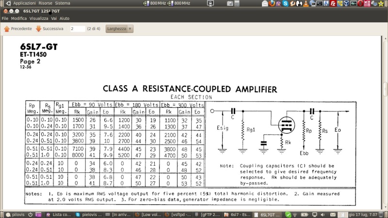
You can do this yourself easily. First locate the triode curve data sheet of the PL504.
At the horizontal axis are listed the anode voltages. Find 150 Volt.
Then look left on the vertical axis and find 50 ma. Now draw a horizontal line, parallel to the horizontal voltage axis, from the 50 mA point toward the 50 mA point above the 150 Volt point on the horizontal axis. Now see within which grid voltage line this point falls. This is the voltage dropped over the cathode resistor. Then calculate the cathode resistor V/A=R. Than check the VA value of the cathode resistor. Volt / Amp. To be sure double the VA value. You can do this for every setting of the tube.
I guess 50 mA is a nice point to start. If the sound is ok you could try to increase the current. to say 75 or 100 mA. At some point the OPT core will saturate and distortion will kick in heavily. The cathode resistor has to be calculated for each current.
You can do this yourself easily. First locate the triode curve data sheet of the PL504.
At the horizontal axis are listed the anode voltages. Find 150 Volt.
Then look left on the vertical axis and find 50 ma. Now draw a horizontal line, parallel to the horizontal voltage axis, from the 50 mA point toward the 50 mA point above the 150 Volt point on the horizontal axis. Now see within which grid voltage line this point falls. This is the voltage dropped over the cathode resistor. Then calculate the cathode resistor V/A=R. Than check the VA value of the cathode resistor. Volt / Amp. To be sure double the VA value. You can do this for every setting of the tube.
Sure. Will start learning that.Your suggested values for 6j1 works great. I request you to confirm the settings Ra10k and RK 1k on 6J1,by testing on your prototype.Once you confirm, this version can be validated for 60 to 80 volt.,To my ears,it sounds very good.
tnvijay I'm travelling and I will not be back for some time to check on the small amp. Can you confirm the voltages on the 6J1? HT (supply voltage after 2.2K resistor), Va (anode voltage) and Rc (cathode voltage). This allow you the calculate the voltage drop over the anode resistor and the mA through the tube. The setting with the 4.7K anode resistor resulted in on 2VAC drive of the PL504. Consequence the 6J1 at full swing increases distortion. So we need more output voltage. You can measure that after the coupling capacitor. Multimeter range on AC measuring. With music this measurment will swing enormously, but you well get a feel of the values. Also a multimeter to measure here is not ideal as it has often a low impedance. A FET voltmeter or tube voltmeter will have a very high impedance and not affect the small current flowing to the grid. However in the practical world you have to do with what you have.
I didn't reply to one of your earlier posts.
It is never a good idea to have an OPT without a speaker. This can cause very high voltage spikes in the transformer and burn the primary windings and cause damage to your power tube or HT supply. This is worse in amplifiers with high voltages. Singing of the transformer can be caused by windings which are not properly fixed.
Normally transformers are vacuum impregnated with electrical vanish, which will fix the windings in place. When you load a transformer with DC it will give a jolt to the windings and magnetize the transformer core. As the polarity of the magnetic field does not change (DC), this will not cause any further movement of the windings. This is however different with AC. This changes polarity all the time and could subtly move the windings.
That's why you need to put a bit of varnish on a completed layer before you add the insultation layer on which the next layer will be wound. Cheap and vintage power transfomers are sometimes not properly varnished (or tarred) and may cause an audible vibration resulting in hum. Not ideal in an hifi amplifier, as these vibrations can be picked up by sensitive pre-amp tubes. The effect of tubes to pick up vibrations is called "microphony".
The power transformer you used as OPT; 220 V to 9 Volt has a much too high impedance for the PL504. The impedance of a transformer can be calculated by putting a small AC voltage e.g. 6 - 9 Volt, on the secondary and measuring the Volts generated at the primary. With a power transformer we know these voltages already. Then you calculate as follows:
Prim V / Sec V = Winding Ratio (WR)
WR x WR x speaker impedance will give you the impedance of the primary with given speaker load.
So 220 / 9 = 24.44
24.44 x 24.44 x 8 = 4780 Ohm
For a 24 Volt power transformer the impedance is:
220 /24 = 9.17
9.17 x 9.17 x 8 = 672 Ohm
Open secondary on a triode connected OPT is safe, the triode heavily damps any voltage excursion. But with a pentode output could result in OPT primary winding insulation failure.
The HV developed in the collapsed magnetic field of an inductor is used to great advantage in spark ignition engines.🙂
The HV developed in the collapsed magnetic field of an inductor is used to great advantage in spark ignition engines.🙂
Thanks for the info. Didn't know this was different for triodes and pentodes. Keep learning.
A collapsed magnetic field is perfectly shown with a shorted winding tester.
A collapsed magnetic field is perfectly shown with a shorted winding tester.
tnvijay I'm travelling and I will not be back for some time to check on the small amp. Can you confirm the voltages on the 6J1? HT (supply voltage after 2.2K resistor), Va (anode voltage) and Rc (cathode voltage). This allow you the calculate the voltage drop over the anode resistor and the mA through the tube. The setting with the 4.7K anode resistor resulted in on 2VAC drive of the PL504. Consequence the 6J1 at full swing increases distortion. So we need more output voltage. You can measure that after the coupling capacitor. Multimeter range on AC measuring. With music this measurment will swing enormously, but you well get a feel of the values. Also a multimeter to measure here is not ideal as it has often a low impedance. A FET voltmeter or tube voltmeter will have a very high impedance and not affect the small current flowing to the grid. However in the practical world you have to do with what you have.
I did some measurements today. Voltage 82 volts. After 2.2k, it is 79 volt.
6j1 anode measures 55 volt. 6j1 cathode measures 1 volt. Multimeter AC range measures, 110 volt( which i doubt is wrong since, i measured it on 6j1 anode, and not after the capacitor, as said.) I tested various values of Ra. 10 K to 22k is the range. 22K gives maximum volume, However, with varying sources, like a cd player, it distorts at the maximum volume. For mobile and tablet headphone outputs, 22k gives maximum gain. I also used a good 220:24 volt, and its surprisingly good.Today , i also substituted similar values on the second channel. I should say, for s low voltage, beginner amp, this one is really cool little amp. Enough volume on a 250 sq.ft room. With a little more voltage, say, 120 to 150 volt, and with a proper OPT, this one is really worth doing. will try to increase voltage and give feedback in a few days. I also started to wind one OPT. Hand winding turn by turn is painstaking, but have done one third of primary layer. Will do that slowly.
Sounds very good. You made some serious progress.
You might want to try to re-stack the 220 - 24 v power transformer used as OPT.
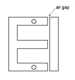
Just put 2 pieces of paper in the opening between the E's and the I's, might be enough gap. The gap width is calculated 2 x for the thickness of 2 sheets of paper in both E legs. So that makes a gap of 4 sheets of paper.
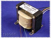
Disadvantage of this approach is however that you need to make brackets to screw the transformer back together. On the first picture you can see the air gap and on the second how Hammond transformers uses the brackets at both sides of the transformer.
To make brackets for homemade transformers, I buy small straight strips of metal at the hardware store, used in wood working to join pieces of wood. They have 2 pre-drilled holes. You can use the top hole (sometimes you have to make it wider to make it fit), make a new hole for the bottom and bend the bottom piece 90 degr, drill a hole in it, so you can fix the transformer to the chassis. Excess to be cut off. Takes a bit of drilling, filing and cutting, but the result works fine. When the 24 V transformer has no screws just buy a piece of 3 mm stainless or other non magnetic threaded bar. Cut to length and use preferably screws and washers of the same material to fix. The stainless steel is not very magnetic and will not act as a shorted winding. With a good homemade brackets you can screw the transformer back together with no change in the air gap.
In tube amplification distortion tends to increase with bigger output voltages. So as long as you don't need the full power you are in the "good" range.
Normally you would want half the HT voltage over Ra and the rest over the pre-amp tube. That can be set by the value of Rk. If you used a cathode resistor of 2.7K, you could increase to 3.3K and see in this increases the voltage over Ra. More current thought the 6J1 reduces the internal resistance in the tube and leaves more voltage swing for Ra.
Please confirm the resistors you used in the amp and the set point of the PL504. With those data and your voltages we can update the schematic. Please confirm:
6J1: Ra Rk You run it in triode?
PL504: Rk and voltage here? Also in triode ? G2 with 100R to A?
Did you find the the working point of the PL504 in the triode graph?
You might want to try to re-stack the 220 - 24 v power transformer used as OPT.
Just put 2 pieces of paper in the opening between the E's and the I's, might be enough gap. The gap width is calculated 2 x for the thickness of 2 sheets of paper in both E legs. So that makes a gap of 4 sheets of paper.
Disadvantage of this approach is however that you need to make brackets to screw the transformer back together. On the first picture you can see the air gap and on the second how Hammond transformers uses the brackets at both sides of the transformer.
To make brackets for homemade transformers, I buy small straight strips of metal at the hardware store, used in wood working to join pieces of wood. They have 2 pre-drilled holes. You can use the top hole (sometimes you have to make it wider to make it fit), make a new hole for the bottom and bend the bottom piece 90 degr, drill a hole in it, so you can fix the transformer to the chassis. Excess to be cut off. Takes a bit of drilling, filing and cutting, but the result works fine. When the 24 V transformer has no screws just buy a piece of 3 mm stainless or other non magnetic threaded bar. Cut to length and use preferably screws and washers of the same material to fix. The stainless steel is not very magnetic and will not act as a shorted winding. With a good homemade brackets you can screw the transformer back together with no change in the air gap.
In tube amplification distortion tends to increase with bigger output voltages. So as long as you don't need the full power you are in the "good" range.
Normally you would want half the HT voltage over Ra and the rest over the pre-amp tube. That can be set by the value of Rk. If you used a cathode resistor of 2.7K, you could increase to 3.3K and see in this increases the voltage over Ra. More current thought the 6J1 reduces the internal resistance in the tube and leaves more voltage swing for Ra.
Please confirm the resistors you used in the amp and the set point of the PL504. With those data and your voltages we can update the schematic. Please confirm:
6J1: Ra Rk You run it in triode?
PL504: Rk and voltage here? Also in triode ? G2 with 100R to A?
Did you find the the working point of the PL504 in the triode graph?
Attachments
6J1 triode mode: pin 5 and 6 joined.
Voltage after 2.2K - 79 VOLT. voltage on pin 5,6( anode) - 55 volt.
Rk on 6j1 is 1k + 100 ohm. Measures 1.0 volt across the resistor.
Pl504: anode voltage 79 volt .
Rk on Pl504 is 220 ohms.
Voltage across RK is 7.8 volts.
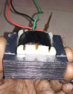
My trafo is unfortunately not having holes on E And I. It was stacked alternatively and covered with a clamp like sheet metal. After restacking, I used the same clamp to put back,but it vibrates.For air gap, I got 0.3mm Nomex sheet. The problem is how to tighten the EI after restacking.( I don't think it's possible CTO drill all the way along the entire stack of E AND I without a proper drilling station with clamps.
I have electric drills,Dremel and other hand tools. But no proper working table with clamps,mounts ,etc
Voltage after 2.2K - 79 VOLT. voltage on pin 5,6( anode) - 55 volt.
Rk on 6j1 is 1k + 100 ohm. Measures 1.0 volt across the resistor.
Pl504: anode voltage 79 volt .
Rk on Pl504 is 220 ohms.
Voltage across RK is 7.8 volts.
My trafo is unfortunately not having holes on E And I. It was stacked alternatively and covered with a clamp like sheet metal. After restacking, I used the same clamp to put back,but it vibrates.For air gap, I got 0.3mm Nomex sheet. The problem is how to tighten the EI after restacking.( I don't think it's possible CTO drill all the way along the entire stack of E AND I without a proper drilling station with clamps.
I have electric drills,Dremel and other hand tools. But no proper working table with clamps,mounts ,etc
That's a nice size transformer. No holes in the laminiations is a problem.
I've no direct solution for that, other than the fact that many SE transformers come
packed in a metal casing. See the enclosed link.
https://www.aireradio.org/riviste_estere/BVWS/o-p_trasf.pdf
I've no direct solution for that, other than the fact that many SE transformers come
packed in a metal casing. See the enclosed link.
https://www.aireradio.org/riviste_estere/BVWS/o-p_trasf.pdf
The KT55 is indeed an interesting tube. In tetrode mode however at 65 Volt grid current will come into play. Possibly a candidate in triode mode. However on Ebay the KT55 is offered for around 150 - 200 Euro. So not an easy to get tube and surely a waste to use at such low voltages.
As this thread deals with a low voltage tube amplifier for newbies, I suggest to have a look at the ECL82 - PCL82 - 6BM8. A tube which is easy to get for a decent price. The PCL82 was used in televisions and one can easily find a used one for a few Euro's. The specs of the PCL82 specify use at 100 Volt for both the triode and the pentode in the same glass envelope. An exhaustive spec can be found at this location. At 100 Volt the pentode produces 1 Watt output with an OPT of 3.9 K (not exactly standard).
https://frank.pocnet.net/sheets/030/p/PCL82.pdf
It might be interesting in this thread to come up with a cheap schematic using commonly available parts to build an amp suitable for newbies, which could later on be turned into a higher voltage amp with a much better performance.
Short update.:
I experimented with higher voltage of approx 135 volt on the 6j1 -pl504 amplifier,.Things did improve. The 6j1 gives maximum ac voltage of 5 volts. ( I remember you mentioned that PL504 needs minimum 10 volt.) So,this is still working,but not as good as a ECC83.
Yesterday I did a quick connect of ECL82, WITH Voltage of 135 volt. I am surprised by the sound quality and output. As of now, I think as you suggested, this thread can be used to develop a beginner tube amp at various power supply levels.
Let's start with ECL82 at 100 - 150 volt.
I used a 220 : 9 volt trafo, for OPT.
I used this schematic to start with. Bypass cap across 220 ohms increase loudness,but distorts at maximum volume. Anything can be done more on this? The plate to cathode voltage of pentode is 115 volt, Current through tube is 34 mA. (7.5 VOLT/220 OHM) .Plate dissipation comes to around 4 watts. Am I within limits?connecting G2 to B+ gives loud sound. Triode connected reduces the volume, but mellows the sharp and harsh highs. Rk Capacitor bypass significantly improves volume in both situations
Attachments
you should look for the ecl82 or pcl82 data sheet
here you find the exact settings of the tube for HT voltages starting at 100 volt
here you find the exact settings of the tube for HT voltages starting at 100 volt
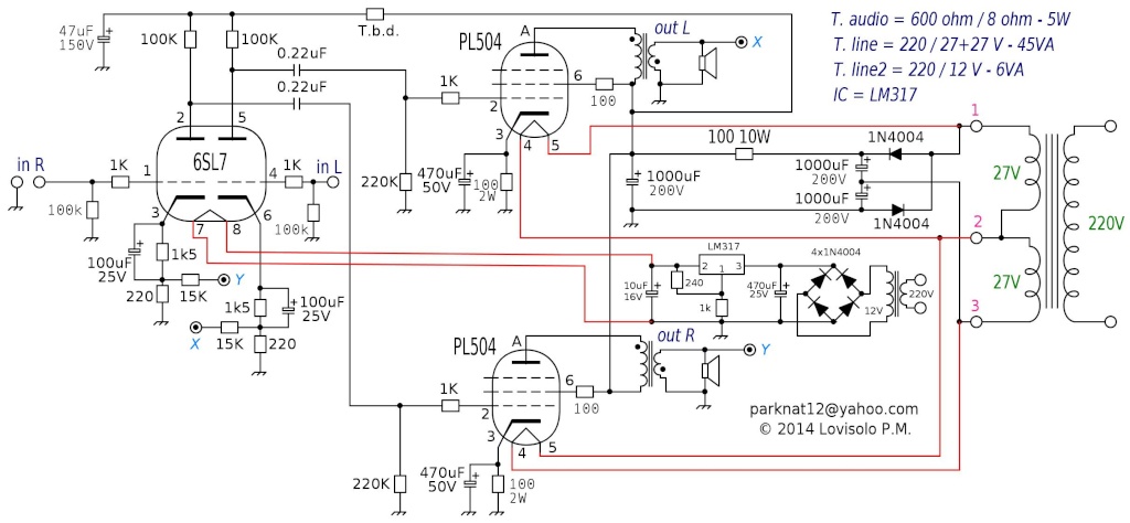
Updated version with voltage doubler and negative feedback to linearize bandwidth reduce distortion to very low level (about 110V anode voltage):
Note: (the following substitutions may have different pinouts and may vary performances and/or audio responses, to be tested)
PL504 can be substituted by PL500, PL36 (be careful, reduce filament to 25Vac by using 24-24Vac main trafo)
6SL7 can be substituted by 6SN7, ECC81, ECC82, ECC83, 6FDQ7
Main transformer can be 24+24 without problems (lower anode voltage, little smaller heater voltage for PL504).
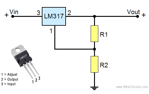
Triode heater voltage can be 6 Vac, in this case you don't need LM317 Voltage stabilizer.
Note: (the following substitutions may have different pinouts and may vary performances and/or audio responses, to be tested)
PL504 can be substituted by PL500, PL36 (be careful, reduce filament to 25Vac by using 24-24Vac main trafo)
6SL7 can be substituted by 6SN7, ECC81, ECC82, ECC83, 6FDQ7
Main transformer can be 24+24 without problems (lower anode voltage, little smaller heater voltage for PL504).
Triode heater voltage can be 6 Vac, in this case you don't need LM317 Voltage stabilizer.
Last edited:

Additional notes:
errata corrige: 6FQ7 (was 6FDQ7 above)
The resistor indicated above with T.b.d. has to be choosed to obtain about 90V at 47uF 150V capacitor.
15K feedback resistors (on triode catode) can be modified to increase or decrease negative feedback.
If you plan to use 12V (Ac or Dc) instead of 6V for triode heater voltage, you may use 12FQ7 or even ECC81, ECC82, ECC83 by connecting the two internal heaters in series:
An externally hosted image should be here but it was not working when we last tested it.
Last edited:
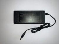
Hello pilovis, glad to see that you are still visiting this forum. I am planning to build your PL504 amplifier with the original safe anode supply, because it does not require insulation on the PL504 anode cap. Starting from your old schematic at the beginning of this thread, I will try a further part and cost optimization. The driver tube will be the triode section of the UABC80 tube, a popular (and plentifully available) detector/preamplifier for European hot chassis tube radios. The triode is electrically identical to a section of 6SL7, but the heater power supply is 28V, about the same value of the PL504 tube. To keep size and complexity low, and to avoid hum, I will try to use a 50V 1A switched mode power supply. This "power brick" power supply has become cheap and easy to source lately, due to the increased popularity of small network switches with power over ethernet capability. They are often installed to power the new breed of Internet connected VoIP desktop phones, network cameras etc. Street price for a 4 port PoE switch with metal case and 50V 1A external power supply brick is less than 30 euro: it is actually cheaper than the power brick alone, sold as spare. By the way, the switch still works just fine (with PoE funcion disabled) with a regular 12V power supply. I sampled a few ot those supplies with the scope, and they look promising. EMI filtering is better than the price suggest, perhaps because any excess switching noise will interfere with the ethernet signal. When the filaments of the PL504s are connected in series, the power supply supports the power on current spike. The PL504 filament supply datasheet value (27V) does suggest that 50V is not enough to turn on the heaters fully, but it is not the case according to my tests. The filament current on my Philips and Siemens tubes settles at 340-370 mA. This means that there is no issue powering 2 tubes at 48V, and I may even add a series diode to drop the 50V slightly and bring the current down to 300 mA.
On post #6 of this thread, you stated that the PL504 measured anode voltage is 53V, and cathode voltage is 3V. The cathode resistor is 39 ohm, so the cathode current is about 70mA. On post #137, the anode is at 110V and the cathode resistor has been increased to 100 ohm. Do you measured the cathode voltage?
On post #6 of this thread, you stated that the PL504 measured anode voltage is 53V, and cathode voltage is 3V. The cathode resistor is 39 ohm, so the cathode current is about 70mA. On post #137, the anode is at 110V and the cathode resistor has been increased to 100 ohm. Do you measured the cathode voltage?
Attachments
The driver tube will be the triode section of the UABC80 tube, a popular (and plentifully available) detector/preamplifier for European hot chassis tube radios. The triode is electrically identical to a section of 6SL7, but the heater power supply is 28V, about the same value of the PL504 tube.
Good choice!
- Home
- Amplifiers
- Tubes / Valves
- Low Voltage (60V) Stereo Tube Amplifier for Dummies (2+2W)