You said you ordered a 5 kOhm SE OPT's. That limits your choice to using an EL84 which requires an OPT with a primary impedance of 5.2 KOhm.
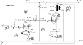
Here are the updated schematics. They include the last voltage measurements also. The amp has undergone some changes to improve the working of the 6J1 at 60 Volt.
The coupling capacitor between the 6J1 and the PL504 has been reduced from 0.1 uF to 0.022 uF. The 0.22 uF and the 100K grid leak resistor form a filter which will cut off the bass below 72 Hz. This will avoid saturating the OPT and will help to reduce distortion. I've tried feedback, but only a feedback resistor of 220 Ohm showed some effect, but I heard no real improvement. If tyhe feedback makes the sound louder, you have to switch the HT connections on the output transformer !!!
There is still some distortion when the amplifier is played fully open. The amplifier is not loud, but plays decent music with a reasonable amount of bass through my small desktop speakers. This is however no hifi.
This project is intended play around with tubes. In this porticular case with two 6J1's and two PL504's and two 24V power transformers.
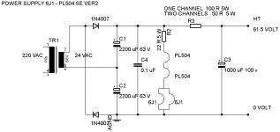
The power supply schematic is also depicted. The 24 VAC is rectified and doubled. This gives about 64 - 65 Volt DC. This is used to feed the chain of filaments.From there the HT is filtered using a resistor of 100 Ohm (one channel) or 50 Ohm (two channels), together with a 1000 uF 100 V electrolytic capacitor. The remaining HT measures 61.4 Volt. The additional filtering makes sure the amplifier is completely hum free.
The coupling capacitor between the 6J1 and the PL504 has been reduced from 0.1 uF to 0.022 uF. The 0.22 uF and the 100K grid leak resistor form a filter which will cut off the bass below 72 Hz. This will avoid saturating the OPT and will help to reduce distortion. I've tried feedback, but only a feedback resistor of 220 Ohm showed some effect, but I heard no real improvement. If tyhe feedback makes the sound louder, you have to switch the HT connections on the output transformer !!!
There is still some distortion when the amplifier is played fully open. The amplifier is not loud, but plays decent music with a reasonable amount of bass through my small desktop speakers. This is however no hifi.
This project is intended play around with tubes. In this porticular case with two 6J1's and two PL504's and two 24V power transformers.
The power supply schematic is also depicted. The 24 VAC is rectified and doubled. This gives about 64 - 65 Volt DC. This is used to feed the chain of filaments.From there the HT is filtered using a resistor of 100 Ohm (one channel) or 50 Ohm (two channels), together with a 1000 uF 100 V electrolytic capacitor. The remaining HT measures 61.4 Volt. The additional filtering makes sure the amplifier is completely hum free.
Attachments
If you plan to build a PCL86 Push Pull amplifier; check out the PDF in this link.
Push Pull ECL86/6GW8
It gives you all the details you need to build the amplifier, including data on winding the power- and output transformers. If you can find someone in your region who can wind transfomers, you might want to have a go at this. You can ofcourse use the PCL86, but than you need to change the fillamenbt supply from 2 x 6,3 Volts to 2 x 13.3 V at 0.3 Amp.
Spent some sunday noon with the PL504. I connected the laptop as the source. It's got high volume output than mobile, so I noticed distortion right away. I quickly disconnected the 6j1 pre and connected the input to PL504 directly. The volume is low, as known, but clear sound. I still feel the preamp section is not optimal. May be the 6J1 is not suitable? I also opened one line matching trafos, Pulled out all the EI laminates, and stacked them as you said. I experimented with various air gaps, and found the sound changes significantly. With just listening tests, I know it's difficult to set the air gap,but I found the copper winding to be very low number, which leads to a lot of empty space between the vertical limbs of the E and bobbin. Poor design, since it's a low end trafo. But, i plan to use the same bobbin, and wind new opt,with interleaving, 2 primary and one secondary. I can use thick wires, since the turns calculation come to 1400 and 140. I used practical OPT making calculation formulafrom valveheart website. As such,the restacking has helped to open up the mods even better. So a new coil winding will be worth doing...
As far as PCL 86, thanks for the link. It's clearly documented,, and I saved a copy of the PDF.As I said, my initial obsession is on a single ended design, since people swear for its unique sound character.. I have seen several schematics, but I finally decided to do" PICOLO" It was suggested by one fourum member in ECL 86 thread... Push pull will be my next step, as it's more complex and more component count.. Thanks.
As far as PCL 86, thanks for the link. It's clearly documented,, and I saved a copy of the PDF.As I said, my initial obsession is on a single ended design, since people swear for its unique sound character.. I have seen several schematics, but I finally decided to do" PICOLO" It was suggested by one fourum member in ECL 86 thread... Push pull will be my next step, as it's more complex and more component count.. Thanks.
Interesting thread! Dos anyone have any idea of the performance of this amp, measurements-wise?
Jan
Jan
Forum member tubedog can give us some measurements. It's indeed very interesting in that it works in low voltage,with enough power for a small room.
26A7 & 28D7 will perform well on 28V B+supply. Were used in aircraft radios. Expensive now. 48 would do as well, but needs DC heater. Made for use in early city centers with an Edison DC supply.🙂
Attachments
The 6J1 - PL504 SE project is intended to help tnvijay to build his first tube amplifier with the tubes he had at hand. The result is a working amplifier which is not loud and gives a reasonable sound. When the volume is full open there is distortion. I would not qualify the amp as HiFi. Don't forget two 24 volt power transfomers are used for the power supply and the OPT (no air gap). I'm not sure about the 6J1 as it only produces 2VAC output with 150 mV input with a HT of 60 Volt. I would have liked a bit more output. The PL504 in triode is not really in a very comfortable spot of its working range either. So all in all a nice and cheap project to get a safe low voltage feel about working with tubes, but not when you want to build a HiFi amplifier.
I guess the whole amp would improve by operating it at 165 Volt or more e.g. 250V. Ofcourse this requires reviewing the resistor values of the tubes and the use of an air gapped OPT.
I guess the whole amp would improve by operating it at 165 Volt or more e.g. 250V. Ofcourse this requires reviewing the resistor values of the tubes and the use of an air gapped OPT.
jhstewart your suggestions for low voltage tubes are very interesting, but they are not common in Europe,so I've not worked with them. In Europe we have the EF97 (6FD6), a control pentode and EF98 (6ET6) small signal pentode which were used in car radio's and only require 6 - 12 Volt on the anode. No experience with them.
Forum member tubedog can give us some measurements. It's indeed very interesting in that it works in low voltage,with enough power for a small room.
Yes interesting. Ron Quan's articles in Linear Audio gave many details of running tube amps at 48VDC but these were preamps, phono preamps and a headphone amp.
He used many of the tubes mentioned here, and included measurements, so you knew what you were doing.
Jan
jhstewart your suggestions for low voltage tubes are very interesting, but they are not common in Europe,so I've not worked with them. In Europe we have the EF97 (6FD6), a control pentode and EF98 (6ET6) small signal pentode which were used in car radio's and only require 6 - 12 Volt on the anode. No experience with them.
In Europe KT55 comes to mind as a possibility for low B+ output.🙂
Attachments
The KT55 is indeed an interesting tube. In tetrode mode however at 65 Volt grid current will come into play. Possibly a candidate in triode mode. However on Ebay the KT55 is offered for around 150 - 200 Euro. So not an easy to get tube and surely a waste to use at such low voltages.
As this thread deals with a low voltage tube amplifier for newbies, I suggest to have a look at the ECL82 - PCL82 - 6BM8. A tube which is easy to get for a decent price. The PCL82 was used in televisions and one can easily find a used one for a few Euro's. The specs of the PCL82 specify use at 100 Volt for both the triode and the pentode in the same glass envelope. An exhaustive spec can be found at this location. At 100 Volt the pentode produces 1 Watt output with an OPT of 3.9 K (not exactly standard).
https://frank.pocnet.net/sheets/030/p/PCL82.pdf
It might be interesting in this thread to come up with a cheap schematic using commonly available parts to build an amp suitable for newbies, which could later on be turned into a higher voltage amp with a much better performance.
tnvijay your test results conforms that the 6J1 does not make an ideal preamp in combination with the PL504. The settings used for the 6J1 are the same as those in the schematics of 6J1 preamps sold on internet working at approx 65 volt. The 2 volt output of the 6J1 is clearly not enough to drive the PL504 in triode mode.
Suggest you try one last change to the 6J1 Ra = 10K Rk = 1K. See if that improves the sound.
If that does not work you might want to try the PCC88. Also an old television tube. No clue if you can get hold of that where you live in India.
Also the fact that adding an air gap to the OPT improved the sound quality is very interesting and confirms the effect of DC in an OPT of a single ended amplifier.
You can calculate OPT's with the following program
OPT Calucator
If you want to wind yourself you should also check
index
and in particular
output-trans-winding
Find a motor rewinding shop and buy pieces of 0.1 mm and 0.5 mm insulation sheet.
You can cut strips of this which fit into your bobbin.
The 0.1 mm is for inter layer insulation and the 0.5 mm to separate the secondary and the primary and to cover the windings when you are finished.
Also ask for a jam pot (with a well closing lid) of electrical varnish.
Get you some cheap disposable small paint brushes.
Fix the in and outgoing leads well with masking tape.
Mark all leads well as you have reconnecting to do later on.
Apply a bit of varnish on every winding before you apply the insulation.
Winding transformers is fun.
Especially when you can use them in your own amps.
Start with simple transformer configurations.
tnvijay your test results conforms that the 6J1 does not make an ideal preamp in combination with the PL504. The settings used for the 6J1 are the same as those in the schematics of 6J1 preamps sold on internet working at approx 65 volt. The 2 volt output of the 6J1 is clearly not enough to drive the PL504 in triode mode.
Suggest you try one last change to the 6J1 Ra = 10K Rk = 1K. See if that improves the sound.
If that does not work you might want to try the PCC88. Also an old television tube. No clue if you can get hold of that where you live in India.
Also the fact that adding an air gap to the OPT improved the sound quality is very interesting and confirms the effect of DC in an OPT of a single ended amplifier.
You can calculate OPT's with the following program
OPT Calucator
If you want to wind yourself you should also check
index
and in particular
output-trans-winding
Find a motor rewinding shop and buy pieces of 0.1 mm and 0.5 mm insulation sheet.
You can cut strips of this which fit into your bobbin.
The 0.1 mm is for inter layer insulation and the 0.5 mm to separate the secondary and the primary and to cover the windings when you are finished.
Also ask for a jam pot (with a well closing lid) of electrical varnish.
Get you some cheap disposable small paint brushes.
Fix the in and outgoing leads well with masking tape.
Mark all leads well as you have reconnecting to do later on.
Apply a bit of varnish on every winding before you apply the insulation.
Winding transformers is fun.
Especially when you can use them in your own amps.
Start with simple transformer configurations.
Thankyou very much! Indeed I will start to wind OPTs. Having an obsession for Valve audio,I will not let the scarcity of OPT as a showstopper. Btw, I welcome your target of designing a low voltage tube amp for newbies. I will try your suggested values in a couple of days. In addition, I also saw a schematic of 6J1 and FU32, 6J1 operates at 150 volt. I have a 220 to 110 volt trafo, so I can rectify and get 160 VDC.
Attachments
tnvijay is also searched internet to find low voltage amplifiers. The general consensus seems to be that most pre-amplifier tubes, which are designed to work at 250 V or more, can give a reasonable performance down to approx 150 Volt. Below that they do not perform less well, as some parts of the audio spectrum are not amplified evenly. Also the amount of output voltage you can get out of a tube decreases.
This may be a good reason to increase the HT to at least 150 Volt.
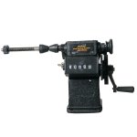
You might want to look for a "hand coil winding machine" on Aliexpress. They are rather cheap and work fine for winding coils. You have to fill the bobbin with a snugly fitting piece of wood, with a hole dead center.
This may be a good reason to increase the HT to at least 150 Volt.
You might want to look for a "hand coil winding machine" on Aliexpress. They are rather cheap and work fine for winding coils. You have to fill the bobbin with a snugly fitting piece of wood, with a hole dead center.
Attachments
Thanks! I saw the machine, and again, shipping costs too much. I can find native variants of this machine locally. Will try for it in due course. Meanwhile, Yesterday I got two reels of 40 swg and 33 swg wires for winding the trafo for pl504. The plan is to use the bobbin and EI cores of the line matching trafo, and wind a new coil. I am planning to do by hand . I know it's going to take too much time,but since it's only 1400 turns : 140 turns, I can do it in parts. Primary is split in to three and secondary into two.Before that, I will try to optimise the 6j1 preamp section. I will use 47k Ra and 2.2k Rk. B+ would be 150 to 160. Can you verify with data sheet if it works? Thanks in advance.
It good to see that you are trying to build your own OPT. You have however to do some calculations to make this work. You write that you are going to use 40 SWG and 33 SWG maget wire. Best is to use double isolated wire. As I'm accustomed to working in the metric system, so I will transfer your SWG wire into mm.
So 40 SWG is magnet wire has a core of 0.18 mm diam. 33 SWG has a core of 0.08 mm diameter. I assume the thinnest wire will be used in the primary winding. This is where the anode of the PL504 will connect. The wire diameter and the size of the core (and air gap in an S.E. transformer) determine how much DC current can run through the wire to magnetize the core.
The wire in a transformer are generally loaded between 2.5 - 3 A / mm2 of wire.
A very thin wire of 0.08 mm can only handle 15 mA of DC current at 3 A / mm2
When that is exceeded the windings in the primary may fuse.
So in order to set the working point of the PL504 you have to consult the tube specification sheet. Look for the curves marked "triode" in which G2 is connected to the anode.
https://frank.pocnet.net/sheets/010/p/PL504.pdf
On the vertical axis you find the Va of say 150 Volt. Then you move up to the point of 15 mA. You then see you end up at a point between the grid lines of -25 and -30 Volt. That means you need -27.5 V at the top of the cathode resistor. The cathode resistor can now be calculated; 27.5 V / 0.015 mA = 1833 Ohm e.g. 1.5 K and 330 Ohm in series. The VA rating of this resistor is 27.5 x 0.015 = 0.4 VA. so a 1 Watt resistor would do.
I can understand that you would like to have more current and thus more output power from your amplifier, but that can only be done when you have a larger OPT with thicker wire in the primary. You can see how that works when you play around with the program OPT Design Assistant.
Regarding the 6J1. Just follow the lead of the schematic you found earlier, where the tube was run with a HT of 150 V. The anode of the tube was at 95 Volt, indicating enough voltage drop over the anode resistor. As this resistor determines the output voltage swing, there should be more drive voltage. However the schematic lists a cathode resistor of 2.7K and not 2.2 K as you proposed to use. I don't think the difference in performance of the tube for an anode resistor of 47K and 51 K will be large.
Looking forward in how you have proceeded.
,I just saw your post. Before that,I tried your final suggestion, a few post back. i.e. Ra 10k and RK 1k. And, I am happy,this works perfectly.! I tested both mobile and laptop as source. There's absolutely no distortion even at full volume. So,at a voltage of 82 B+, this is perfect. The voltage drop against 10k is 22 volt. Cathode volatage is 1 volt. Let's now change the values on the version 2..
As far as SWG,sorry, I made a typing mistake. I bought 26 and 33 SWG. This 26 will be wound in 2 layers and paralleled. 33 swg is for primary. I did some calculation based on formulas from valveheart- practical output trafo. Since the core size is fixed, I assumed the power out as 3 watts max and did the calculations. I calculated the number of turns within that bobbin. And chose the thickest possible. Thanks for the information on current rating / mm. I am new to this, and it helped me to grasp things much better. I am yet to use the software.,which I will start in due course.
Secondly, I found that the line trafo sings audibly when the speaker wire disconnected. What does that mean? I also tried various trafos. 220 to 9 volt 1 ampere trafo gave the cleanest sound.I have to test with 220, 24 trafo which is what is recommended.its still to be recovered from the parts bin. As of now, the 220: 9 volt does the job,quiet neatly. I will wind opt trafo, and then substitute it,with probably better bandwidth.This amplifier seriously needs to be developed, since the 6j1 is available new, as well as very very low priced. Let's fix the max. Voltage as 150. Can we develop this further?
I have difficulties in understanding and interpreting the load line graphs. That's why I keep troubling you.sorry for that. When I started to develop interest in vacuum tubes, I first read Entertaining electronic s , a book by e.sedov. It was very nice and helped me to understand valves. However,I am yet to decipher graphs and interpret. Will slowly learn , My thanks again for the detailed explanatory answer.
- Home
- Amplifiers
- Tubes / Valves
- Low Voltage (60V) Stereo Tube Amplifier for Dummies (2+2W)