I agree with the rumble filter switch off option, or at least make it switchable to a much lesser slope. Never use it with my ESL’s.
I suspect a typo with the 750usec pole, which one is meant here ?
Hans
I suspect a typo with the 750usec pole, which one is meant here ?
Hans
No Neumann pole - the standard all active RIAA is always 0.1-0.5 dB to o high at 20 kHz - the secondary post LPF pulls it back into line. The RIAA is to within 0.15 dB
Switchable rumble. Ok.
Switchable rumble. Ok.
This is the MM RIAA EQ stage. It incorporates MM cart resistive loading, a system gain stage (1x, 2x, 3x and 4x switchable gain) and a 20 Hz 60 db/decade HPF.
...
Wouldn't it be nice to allow for a differential input in case of a connected MM cart as well? It may introduce some additional noise but there might be situations where CM rejection advantage outweights that. If we need another OpAmp in front of U8 for that anyway, we could use the additional gain to make up for a passive RIAA EQ and get some caps out of the signal path.
Bonsai,
Just a point to take care of with the PCB design.
With the 5V version with 220R in the collectors, power consumption in the ZTX transistors was only 15mW.
Now with the latest 10Volt incarnation with Ic 15mA, power increases six fold to 92mW with 100R collector resistances.
Transistors will get rather warm, meaning a large Vbe shift.
So they should be thermally coupled and attached to a proper cooling fin.
Hans
All the coupling caps are optionally film at 2.2 uF. I’ve included a 22 uF bipolar at the output since there may be some cases where the pre is driving a low Z load.
I agree with the rumble filter switch off option, or at least make it switchable to a much lesser slope. Never use it with my ESL’s.
I suspect a typo with the 750usec pole, which one is meant here ?
Hans
The pole I am talking about is the 220 Ohm <> 3.3 nF one at the output of the RIAA EQ amp (‘secondary post filter’). All the other poles are in the active RIAA stage.
A next important point to consider.
It would be a shame to go from Ic 9.5mA to 15mA, thereby gaining 0.88dB, and after that throw away many dBs because of the LM4562, wouldn't it?
The LM4562 plus resistors has an EIN of 8.8nV/rtHz.
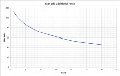
Let's say that 1dB max additional noise from this stage is acceptable, meaning that the noise coming from Vx,Vy should be twice that amount or 17.6nV/rtHz.
For the various Carts this means a minimal gain is required, see first image below.
As an example for a 4R cart, this means a minimal gain of 92 or 39dB which is O.K. with the next stage with 30dB to 42dB gain setting from a point of overall gain.
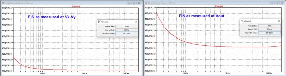
See second image for the EIN before and after the LM4562.
However with the high gain settings as needed for Carts with a low internal resistance, OLM suffers significantly, although the input stage is well harnessed against additional overload, so this probably won't give a real problem.
Alternative would be to make the diff to se stage less noisy.
Hans
.
It would be a shame to go from Ic 9.5mA to 15mA, thereby gaining 0.88dB, and after that throw away many dBs because of the LM4562, wouldn't it?
The LM4562 plus resistors has an EIN of 8.8nV/rtHz.
Let's say that 1dB max additional noise from this stage is acceptable, meaning that the noise coming from Vx,Vy should be twice that amount or 17.6nV/rtHz.
For the various Carts this means a minimal gain is required, see first image below.
As an example for a 4R cart, this means a minimal gain of 92 or 39dB which is O.K. with the next stage with 30dB to 42dB gain setting from a point of overall gain.
See second image for the EIN before and after the LM4562.
However with the high gain settings as needed for Carts with a low internal resistance, OLM suffers significantly, although the input stage is well harnessed against additional overload, so this probably won't give a real problem.
Alternative would be to make the diff to se stage less noisy.
Hans
.
Attachments
Yes, that was obvious. I was reaction to Syn08's posting with 750usec.The pole I am talking about is the 220 Ohm <> 3.3 nF one at the output of the RIAA EQ amp (‘secondary post filter’). All the other poles are in the active RIAA stage.
Hans
Bonsai,
With the 5V version with 220R in the collectors, power consumption in the ZTX transistors was only 15mW.
Now with the latest 10Volt incarnation with Ic 15mA, power increases six fold to 92mW with 100R collector resistances.
Transistors will get rather warm, meaning a large Vbe shift.
So they should be thermally coupled and attached to a proper cooling fin.
Hans
For the current source, why not CPH3910 JFET with Idss of 20mA, trimmable with one resistor instead of Q4 as shown in the illustration of Post 176?
I will put it on the bench this afternoon and compare with the ZTX851/LM4562 shown. (In fact, may not need a dual opamp)
Current source??
Q4 is a pass transistor of the +10 V supply voltage regulator to boost current capability above what the opamp can deliver.
Q4 is a pass transistor of the +10 V supply voltage regulator to boost current capability above what the opamp can deliver.
For the current source, why not CPH3910 JFET with Idss of 20mA, trimmable with one resistor instead of Q4 as shown in the illustration of Post 176?
I put some NSVJ3910 on the curve tracer yesterday. L-Z, finally in a box.
At least, they seem repeatable.
I gave up after 5 pcs. because of the !§$%""!! SOT-23 test socket.
Attachments
Yes, that was obvious. I was reaction to Syn08's posting with 750usec.
Yes, typo.
No Neumann pole - the standard all active RIAA is always 0.1-0.5 dB to o high at 20 kHz - the secondary post LPF pulls it back into line. The RIAA is to within 0.15 dB
Sorry, I wrongly read the values at the second stage pole. Make that a switchable Neumann pole, some people swear by it (as many as those who hate it).
Hans, given the high output currents of some carts, keeping the front end gain high to minimize the noise contribution of the diff amp stage is going to be difficult a d cause OLM issues. .
Other option is to return to the original diff amp, but use low feedback R values
Or
Buffer the present diffamp (discrete tranny for example) and use low feedback resistors.
In practice the signals coming out of the diff amp will be low, so driving a low z network should be ok.
Other option is to return to the original diff amp, but use low feedback R values
Or
Buffer the present diffamp (discrete tranny for example) and use low feedback resistors.
In practice the signals coming out of the diff amp will be low, so driving a low z network should be ok.
I've just done some noise sims looking at the integrated noise 20-20.
With 0.1 Rcart
41nV RMS at Vx,Vy
47nV RMS at Vout
With 5 Ohms Rcart
60nV RMS at Vx, Vy
76nV RMS at Vout
I think were good to go as we are. Obviously the noise contribution of the diff amp stage gets worse with low collector loads, but this is in most cases offset because the output current of carts needing low collector load is very high.
Last edited:
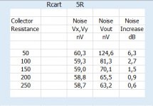
You did not specify the chosen collector resistance for the 5R Cart, so I did it for all available resistances from 50R to 250R.
See table below which shows the noise levels at (Vx,Vy), at (Vout) and finally the noise increase for each chosen resistor value.
So you should at least take 200R, but 250R is even better.
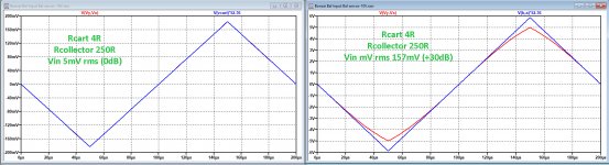
I already mentioned that because of not having feedback, the input stage is quite resistant to overload.
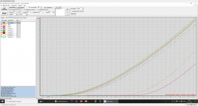
This is illustrated in the second image with a triangle input wave multiplied by the gain on top of the diff. collector signal Vx,Vy.
In this case for a 4R cart and 250R collector resistances.
With a 0dB signal there is a complete overlap, but at +30db the circuit is still alive and kicking although no longer with the gain of 52.36 in the peaks.
Notice that this is no area where music is reproduced, but only there for processing clicks and scratches, so there is nothing wrong with not being linear at that level, as long as there is no overload and recovery situation which is definitely not the case here.
So don't worry, I would leave the situation as it is, my posting was to show that you need high gain settings for low EIN.
But maybe the Diff to Se amp could be reduced to 0dB gain instead of 6dB to compensate for the high gain setting in the first stage.
Hans
.
See table below which shows the noise levels at (Vx,Vy), at (Vout) and finally the noise increase for each chosen resistor value.
So you should at least take 200R, but 250R is even better.
I already mentioned that because of not having feedback, the input stage is quite resistant to overload.
This is illustrated in the second image with a triangle input wave multiplied by the gain on top of the diff. collector signal Vx,Vy.
In this case for a 4R cart and 250R collector resistances.
With a 0dB signal there is a complete overlap, but at +30db the circuit is still alive and kicking although no longer with the gain of 52.36 in the peaks.
Notice that this is no area where music is reproduced, but only there for processing clicks and scratches, so there is nothing wrong with not being linear at that level, as long as there is no overload and recovery situation which is definitely not the case here.
So don't worry, I would leave the situation as it is, my posting was to show that you need high gain settings for low EIN.
But maybe the Diff to Se amp could be reduced to 0dB gain instead of 6dB to compensate for the high gain setting in the first stage.
Hans
.
Attachments
Because this is a current input system, I think a straight RTI noise voltage calculation complicates the issue.
Say you have two carts - both 200uV output but one has a R of 5 Ohms and the other 3 Ohms you get 40uV into the input and 70uV on the second one.
The equivalent thermal noise of the cart resistance has to be converted into a noise current. I will try to do some spreadsheet work tomorrow to scope out the noise envelope considering Vcart, Rcart, Icart and Rcollecter_load
Attachments
Last edited:
This is the original diff amp. The native noise of this one is 332pV/rt Hz vs 440pv/rt Hz on the single opamp version.
Yes, this version produces less noise but you will need large caps.
What exactly is the problem you see with high gain in the first stage ?
And although it is a current gain amp, at the end it’s only the noise that counts.
I think that looking at currents makes things rather confusing.
It’s very simple to make a graph for all possible combinations of Cart resistance with their output voltages that tells you what collector resistance to use and what noise is to be expected.
When you have two 200uV Carts, one with 3R and the other with 5R, you will get resp 105uV and 80uV on both emitters.
Hans
No problem with high gain in the first stage but you have a 1:6 current input range with the carts in the table I posted. At 20 kHz the output current is 10x that’s at 1 kHz then you also want OLM on top of that.
I will put some more stuff up tomorrow.
I want to start layout in the next day or so.
I will put some more stuff up tomorrow.
I want to start layout in the next day or so.
Last edited:
- Home
- Source & Line
- Analogue Source
- Low noise Balanced MC Pre