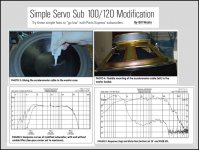
@ bentoronto,
Sorry for the confusion caused by my use of the term “extremes of stroke”…poor wording choice. By this I meant excursions approaching Xmax, or the range over which the driver motor is advertised to behave mostly linearly, not the maximum mechanical stroke of the woofer.
I understand you are an advocate for VC feedback and feel it is superior to accelerometer based solutions. However, your unwillingness to acknowledge any shortcomings with VC feedback seems odd. I personally don’t have a dog in this hunt, but even if I did I would not want to hand wave away linearity issues with either sensor system. I would want to know what they are so I could get the best results from either one I chose to use.
Having built and tested both arrangements with modern long throw woofers, I can say that both provided measureable reduction in distortion. The VC feedback was easier to implement. The accelerometer provided better distortion reduction(measured with B&K4133 microphone) when excursions started to exceed about (1/3)Xmax. Based on recent postings in this thread I wish I had investigated/compared thermal effects on both sensor systems, but I did not.
Last edited:
Tranquility Bass,
Isn't it possible to compensate the temperature problem of the accelerometer if you add a lightweight temperature sensor or/and maybe even an NTC resistor?
Or by software based on the temperature, since this is all digital?
Isn't it possible to compensate the temperature problem of the accelerometer if you add a lightweight temperature sensor or/and maybe even an NTC resistor?
Or by software based on the temperature, since this is all digital?
I'd suggest to not do that. I think TB is smart enough to know that the controller should not have gain at DC. Any LF DC offset drift should therefore not be a problem. The mismatch in sensitivity of the sensor, well, too bad. I'd keep the system simple, instead of making it more difficult.
ps. Still waiting for the open loop bode plot. Only then, we can properly evaluate the expected performance gain.
ps. Still waiting for the open loop bode plot. Only then, we can properly evaluate the expected performance gain.
Yes, a nyquist (snail) or bode plot (easily produced just separate amplitude and angle line traces) would be interesting window into the feedback loop. Along with mic results.
No question the easiest DIY implementation is VC esp with large, good quality drivers - just build it into your electronic crossover box. Or a touch of positive current feedback. Resulting in negative output impedance from your amp. Many people have tried it and works like a charm.
For the future and/or custom-made drivers, I'd bet on capacitative sensing or better-and-cheaper integrated sensors (perhaps accelerometers as pairs to cancel box movement) as they start to appear on sale at DigiKey. As of this morning, I await good evidence that an inexpensive accelerometer connected to an expensive woofer is helpful.
Or maybe GPS.
Ben
Last edited:
I'd suggest to not do that. I think TB is smart enough to know that the controller should not have gain at DC. Any LF DC offset drift should therefore not be a problem. The mismatch in sensitivity of the sensor, well, too bad. I'd keep the system simple, instead of making it more difficult.
ps. Still waiting for the open loop bode plot. Only then, we can properly evaluate the expected performance gain.
It's not as simple as that because the temperature effects the gain of the accelerometer as well which would change the output level which is not very desirable. Also stability margin could be affected - again not desirable. I have a physical fix for this issue which I shall post after I have got it done.
I may include the frequency response plot of the servo amp in the software but I don't want too include to much unnecessary information that may confuse people. I'm trying to keep the user interface as simple as possible.
regards
david
Last edited:
That's at least the second time you've said that.snip
but I don't want too include to much unnecessary information that may confuse people. snip
regards
david
Perhaps you don't understand how that sounds to readers. Let me help you. People would take that to mean either (1) you think we are stupid or (2) you are trying real hard to hide something.
In as much as you have posted high-tech information before, I (and perhaps many other readers) would have to conclude that "2" is right.
There are lots of good reasons for not posting something. But saying you don't want to confuse people, well.... you now know.
Ben
Last edited:
That's at least the second time you've said that.
Perhaps you don't understand how that sounds to readers. Let me help you. People would take that to mean either (1) you think we are stupid or (2) you are trying real hard to hide something.
In as much as you have posted high-tech information before, I (and perhaps many other readers) would have to conclude that "2" is right.
Ben
You shouldn't get offended because not everyone understands control system theory and Nyquist stability criteria etc. Unless you studied electrical engineering and s-plane analysis and Laplace transforms etc, those things don't really mean much to a lay person who wants to put something together and this is who I am aiming this project at. If I can achive that objective this will be a first 😉
Instead you should focus on the end results which are measurable both before and after for which I have already given an example of. I don't give away the source code either because it only works on my hardware. Similarly Hypex doesn't give away circuit diagrams to its amplifiers etc. They provide a solution which can always be measured to validate their design objectives and published specifications 😉
I did say the project was semi open source which means that whilst the hardware and software are proprietary the use of it with third party accelerometers, amplifiers and speakers is not and you are at liberty to source these things yourself. Perhaps I may include some additional information after I have finished everything but since I don't own any patents on it the best form of IP protection is to keep your mouth shut. You may get offended by that statement but since this is a public forum there are other people looking at this thread besides yourself who may have commercial interests and never contribute anything here. Believe me I have been burnt like this before so once bitten twice shy 🙁
regards
david
I respect that......since I don't own any patents on it the best form of IP protection is to keep your mouth shut. You may get offended by that statement but since this is a public forum there are other people looking at this thread besides yourself who may have commercial interests and never contribute anything here. Believe me I have been burnt like this before so once bitten twice shy 🙁
regards
david

I respect that...
me too

I am certainly interested to give your DSP solution a test run when it is ready.
I’m not quite sure what you are trying to say. Are you suggesting that expensive woofers are better(ie more linear) than the accelerometer sensors? Most readily available accelerometers, like the ACH-01, have distortion ratings in the 0.1% range even for large accelerations. Do you feel that the same expensive woofers that wouldn’t benefit from an accelerometer sensor would gain from VC feedback?… As of this morning, I await good evidence that an inexpensive accelerometer connected to an expensive woofer is helpful.
Thanks in advance for clarification on your view point.
Personally I think either system would provide some measureable distortion reduction for even the most expensive woofers.
The audibility of that reduction might be in question though.
I wished I had printouts or screen captures of my distortion data to share with you, but I was not such a good secretary in my younger days. I hope to revisit MF this winter when I wrap up some of my ESL experiments. Perhaps by then Tranquility Bass will have a DSP system I can throw into the comparison.
As both you and Calvin have pointed out, starting with better woofers makes the job of the MF loop easier. If a given sensor can reduce distortion of a cheap woofer to a given level, it should have an easier time reducing the distortion of a more expensive woofer to the same level. With that in mind, you might take a look at the MF article by Bill Waslo (audioXpress 12/06). Mr. Waslo included some background in feedback theory and useful tips on measuring open loop response and generating/understanding bode plots. Here are a few screen shots from the article showing that an ACH-01 attached to a relatively cheap 10” woofer with a single 8-pin dual op-amp feedback circuit can provide flat extended response with distortion in the 1% range down to 30hz. Loop gain is rolled off as 20Hz is approached so as not to overtask the small woofer.
BTW, do you happen to have any measurements for you MF woofer system that you could share?
Nice 😀Or maybe GPS.
Attachments
I don't know enough about the definition, testing, and manufacturing of ".1%" distortion in accelerometers (not to mention all the other analog and digital pieces required to use an accelerometer) to say how that compares to speaker distortion measurements. For sure, each kind of gear has specs appropriate to its own sphere of use and might not be too meaningful for an audiophile. I can picture using a laser to trim a resistor quite precisely, but no intuition about accelerometers.
Although then (and now) an amateur, I did use (then) the largest anechoic chamber in the world at Bell Labs in Murray Hill, NJ, and some really splendid test gear for 1968. My "data" was stuff like signal traces from a very fast moving paper charter and triggered Polaroid pix from a storage scope of tone bursts and pulses. These clear and very revealing visual-data methods were OK for exploring and debugging systems... at the time. Later periods, when I worked on VC MF at home, I didn't have access to tools besides any fancier than distortion testers - and ears. Sorry, nothing for show-and-tell today.
Ben
Last edited:
Hi,
In issue 01/1986 Elektor published a MFB system using a Piezo from a slaughtered Piezo tweeter and a PSL 320 driver of Isophon.
The article and its helpful results have been around for years, but obviously missed the eye of one or the other, as did other articles with similar results.
I agree with You Ben (mark it in the calender, since it is just the 2nd time in a few years 😀 ) on choice nr.2, but (now getting in line again) I think, that TB has every right to do so! It is totally legal to keep Your chances for a possible commercial exploration of Your intellectual property, especially if one has put so much effort into such a demanding project with seemingly high degree of novelty. I assume that many of the 'cracks' and professionals posting in this forum have had the experience of seeing their ideas or basic elements of their circuits been copied or faked and commercially exploited by others.
But even if it weren't for this reason, TB has every right to decide by himself what, how much and to who he is willing to tell something.
jauu
Calvin
As of this morning, I await good evidence that an inexpensive accelerometer connected to an expensive woofer is helpful.
In issue 01/1986 Elektor published a MFB system using a Piezo from a slaughtered Piezo tweeter and a PSL 320 driver of Isophon.
The article and its helpful results have been around for years, but obviously missed the eye of one or the other, as did other articles with similar results.
I agree with You Ben (mark it in the calender, since it is just the 2nd time in a few years 😀 ) on choice nr.2, but (now getting in line again) I think, that TB has every right to do so! It is totally legal to keep Your chances for a possible commercial exploration of Your intellectual property, especially if one has put so much effort into such a demanding project with seemingly high degree of novelty. I assume that many of the 'cracks' and professionals posting in this forum have had the experience of seeing their ideas or basic elements of their circuits been copied or faked and commercially exploited by others.
But even if it weren't for this reason, TB has every right to decide by himself what, how much and to who he is willing to tell something.
jauu
Calvin
NOBODY ever asked for his code, component specifics, or had any serious expectation of seeing that; that is a red-herring first invented by TB. Only some background evidence on his "miraculous" first charts.
This thread has now crossed the tipping point from information to useless fussing about.
Is it time for TB to take his proprietary information to the vendor forum? Those who want to play with his marbles on his patch of dirt, can do so all they please. That's fine. See you there. But not on this DIY forum - it isn't the place for dollar-motivated teasers masquerading as DIY home-brew projects.
Ben
Last edited:
Ben, you keep blowing hot and cold on this thread. I think everyone got your point (how many posts do you have in this thread?), and David also made his quite clear on the subject.
What is the difference between this thread and -for example- OPC's "The Wire" threads?
Do you have a personal agenda or gripe on these MF subjects that make this thread problematic for you?
What is the difference between this thread and -for example- OPC's "The Wire" threads?
Do you have a personal agenda or gripe on these MF subjects that make this thread problematic for you?
Ben, you keep blowing hot and cold on this thread. I think everyone got your point (how many posts do you have in this thread?), and David also made his quite clear on the subject.
What is the difference between this thread and -for example- OPC's "The Wire" threads?
Do you have a personal agenda or gripe on these MF subjects that make this thread problematic for you?
Yes. My gripe is that this thread seems increasingly clear to be an abuse of DIY standards by becoming nothing more than a teaser for selling a product in development.
If David and/or others return to posting information or test results, I'm OK. Or if they choose to stalk off in a great moral huff.
Believe me, I just as well butt out of here but you asked.... Can we now please return to substantive posts.
Ben
Last edited:
Yes. My gripe is that this thread seems increasingly clear to be an abuse of DIY standards by becoming nothing more than a teaser for selling a product in development.
If David and/or others return to posting information or test results, I'm OK. Or if they choose to stalk off in a great moral huff.
Believe me, I just as well butt out of here but you asked.... Can we now please return to substantive posts.
Ben
That is absolute nonsense. I believe John Curl's Blow Torch thread has been going for years with not one constructional project from Mr Curl nor does he give all of his secrets away !! You want to talk about teasers ? Also have a look at some of the other threads with finished projects that started out as "teasers" and are now finished products but are still present in the diy sections. I won't name them but there are a few 😉
And I did say I will post some more measurements in due course. I have just ordered some better microphones because I don't think the RS meter is up to the task.
regards
david
Last edited:
Unless you are using something exotic I don't know about....
An accelerometer measures acceleration, which is the second derivative (instantaneous rate of change) of displacement. Displacement is your key parameter in the servo controller/motor. So you will have to double integrate the accelerometer output - once to get velocity and again to get displacement.
I have to presume you know that, but this is info for your readers.
accel vs mic
You are right, but the fact is that the signal from the accelerometer is exactly the same as the input signal. No need to integrate. When the input signal goes through zero, the speed of the cone is at maximum and the acceleration is zero. I should know, I have been looking at the signals on my scope for over 20 hours this week 🙂
I have no intentions of stealing this thread, but there have been questions about the correlation between "real" microphone output vs accelerometer measurements in this thread.
I have finished the initial testing of my "old fashioned" analogue MF system and have measurements from both accelerometer and microphone. The woofer is a Peerless XXLS 12" (830845) in a 135 liter box that weigh about 60kg.
The microphone was located about 1,5 inch from the woofer during the test. If located further away, the distortion goes up due to room reflections.
The numbers.
20Hz, 18,5V RMS on terminals, NO MF gives THD of 31,4% measured with accel
20Hz, 18,5V RMS on terminals, NO MF gives THD of 24,2% measured with mic
20Hz, 18,5V RMS on terminals, with MF gives THD of 1,34% measured with accel
20Hz, 18,5V RMS on terminals, with MF gives THD of 1,63% measured with mic
Here is a picture whre you can see the difference. (NOTE. The blue curve is inverted because the direction of the accel is positive inwards)

As you can see there is a sharper knee on the blue curve from the acceleremeter while the microphone curve is more smoothed out. I am not sure why this happens, but probably becuase the accelerometer is mounted just on top of the voice coil and can pick up higher frequencies than the whole cone transfer to the air.
PS. I was fooled by a poor measurement microphone for a long time. I was using a 300$ calibrated "Brand X" thinking it was good enough. But the distortion levels only came down to a certain level and stopped even when the accelerometer distortion went further down. I therefore built my own following Linkwitz guide with a Panasonic WM-61 capsule and a MAX427 opamp. With that the distortion levels matched.
Unless you are using something exotic I don't know about....
An accelerometer measures acceleration, which is the second derivative (instantaneous rate of change) of displacement. Displacement is your key parameter in the servo controller/motor. So you will have to double integrate the accelerometer output - once to get velocity and again to get displacement.
I have to presume you know that, but this is info for your readers.
You are right, but the fact is that the signal from the accelerometer is exactly the same as the input signal. No need to integrate. When the input signal goes through zero, the speed of the cone is at maximum and the acceleration is zero. I should know, I have been looking at the signals on my scope for over 20 hours this week 🙂
I have no intentions of stealing this thread, but there have been questions about the correlation between "real" microphone output vs accelerometer measurements in this thread.
I have finished the initial testing of my "old fashioned" analogue MF system and have measurements from both accelerometer and microphone. The woofer is a Peerless XXLS 12" (830845) in a 135 liter box that weigh about 60kg.
The microphone was located about 1,5 inch from the woofer during the test. If located further away, the distortion goes up due to room reflections.
The numbers.
20Hz, 18,5V RMS on terminals, NO MF gives THD of 31,4% measured with accel
20Hz, 18,5V RMS on terminals, NO MF gives THD of 24,2% measured with mic
20Hz, 18,5V RMS on terminals, with MF gives THD of 1,34% measured with accel
20Hz, 18,5V RMS on terminals, with MF gives THD of 1,63% measured with mic
Here is a picture whre you can see the difference. (NOTE. The blue curve is inverted because the direction of the accel is positive inwards)
As you can see there is a sharper knee on the blue curve from the acceleremeter while the microphone curve is more smoothed out. I am not sure why this happens, but probably becuase the accelerometer is mounted just on top of the voice coil and can pick up higher frequencies than the whole cone transfer to the air.
PS. I was fooled by a poor measurement microphone for a long time. I was using a 300$ calibrated "Brand X" thinking it was good enough. But the distortion levels only came down to a certain level and stopped even when the accelerometer distortion went further down. I therefore built my own following Linkwitz guide with a Panasonic WM-61 capsule and a MAX427 opamp. With that the distortion levels matched.
Hi Armand,
IMO this is a case where you should be thinking "inside the box". Putting the mic/pressure transducer in the box makes for a more tightly coupled system.
IMO this is a case where you should be thinking "inside the box". Putting the mic/pressure transducer in the box makes for a more tightly coupled system.
Armand - thanks for posting solid information.
The issue with acclerometer curves is that the feedback cleans them up. Feedback cleans up the reference signal. So you can have great accelerometer curves but that isn't necessarily what the cone or (more modestly and realistically) what the dust cap is up to. Not necessarily. So the only way to be sure is to examine sound.
I am puzzled by your visible curve distortion. My vague impression is that they look more like amp distortion than speaker distortion. Of course, for the normal range of use with reasonably well-performing gear, you just can't eyeball distortion, unless you remove the fundamental or display the output spectrally.
Dan - what's inside the box likely is a mish-mash of tones and phases and echoes that changes inch by inch, and may not be closely related to sound output.
Ben
Last edited:
- Status
- Not open for further replies.
- Home
- Loudspeakers
- Subwoofers
- Low distortion, DSP based high gain servo controlled woofer controller.