You are right, but the fact is that the signal from the accelerometer is exactly the same as the input signal. No need to integrate. When the input signal goes through zero, the speed of the cone is at maximum and the acceleration is zero. I should know, I have been looking at the signals on my scope for over 20 hours this week 🙂
....
This is true in steady state, i.e., sinusoid waves, but I doubt it is that simple for complex waveforms in music. Lets say a complex wavefore consists only of harmonically-related sinusoids. when you double differentiate that representation, you'll see that the higher harmonics have increasing amplitudes, throwing off the frequency response balance to favor the higher frequencies. Throw in some signals representing the percussion instruments, and you'll see it is not at all like the input signal.
An accelerometer measures acceleration, which is the second derivative (instantaneous rate of change) of displacement. Displacement is your key parameter in the servo controller/motor. So you will have to double integrate the accelerometer output - once to get velocity and again to get displacement.
What you should choose for your key parameter depends on what you want your output to be.
If you wanted constant displacement vs frequency, then yes you would want to double integrate the accelerometer output before closing the feedback loop. But, that would result in SPL with a 12dB/oct slope. Choosing constant cone acceleration results in flat SPL response.
Think of a critically damped sealed box woofer without MFB. Below resonance where the cone motion is stiffness controlled, constant force from the woofer motor results in constant displacement vs frequency(ie x = F*k). The SPL response below resonance is the well known -12dB/oct roll off of a sealed box. Above resonance where the woofer cone moving mass dominates the motion, a constant force from the woofer motor results in constant acceleration vs frequency(ie a = F/m). This corresponds with the SPL response above resonance being flat.
BTW, this change from stiffness controlled motion to mass controlled motion right in the middle of our subwoofer bandwidth is one of the main issues encountered when trying to wrap a stable feedback loop around it.
Last edited:
Any careful person would be very modest in disagreeing with Bolserst, but the issues he brings to our attention can be addressed by the simplest circuits in the feedback network... as has been discussed at least since 1957 in connection with MF and more generally by Olson and Beranek long before. So "acceleration" versus "velocity" and "mass" versus "radiation resistance" are not critical issues.What you should choose for your key parameter depends on what you want your output to be.
If you wanted constant displacement vs frequency, then yes you would want to double integrate the accelerometer output before closing the feedback loop. But, that would result in SPL with a 12dB/oct slope. Choosing constant cone acceleration results in flat SPL response.
Think of a critically damped sealed box woofer without MFB. Below resonance where the cone motion is stiffness controlled, constant force from the woofer motor results in constant displacement vs frequency(ie x = F*k). The SPL response below resonance is the well known -12dB/oct roll off of a sealed box. Above resonance where the woofer cone moving mass dominates the motion, a constant force from the woofer motor results in constant acceleration vs frequency(ie a = F/m). This corresponds with the SPL response above resonance being flat.
BTW, this change from stiffness controlled motion to mass controlled motion right in the middle of our subwoofer bandwidth is one of the main issues encountered when trying to wrap a stable feedback loop around it.
These important factors that Bolserst mentions are what I alluded to in suggesting a few times earlier that there is art (well, judgment and compromise) as well as science in speaker design as anyone who has read Toole and has followed the gedlee debates here can see. There is no unique mathematical solution to many issues in music reproduction, at least with present drivers.
Interestingly, some of Bolserst issues can be addressed by simple correction circuits and other issues (such as around resonance) by motional feedback! So, back to the thread.
It's good to bring matters back to the acoustic (and someday even, psycho-acoustic) realm rather than only in disembodied software coding.
Ben
Let me just say this until I've digested your post... Displacement, not velocity or acceleration, yields pressure.
Any careful person would be very modest in disagreeing with Bolserst, but the issues he brings to our attention can be addressed by the simplest circuits in the feedback network... as has been discussed at least since 1957 in connection with MF and more generally by Olson and Beranek long before. So "acceleration" versus "velocity" and "mass" versus "radiation resistance" are not critical issues.
These important factors that Bolserst mentions are what I alluded to in suggesting a few times earlier that there is art (well, judgment and compromise) as well as science in speaker design as anyone who has read Toole and has followed the gedlee debates here can see. There is no unique mathematical solution to many issues in music reproduction, at least with present drivers.
Interestingly, some of Bolserst issues can be addressed by simple correction circuits and other issues (such as around resonance) by motional feedback! So, back to the thread.
It's good to bring matters back to the acoustic (and someday even, psycho-acoustic) realm rather than only in disembodied software coding.
Ben
So you think it's just some disembodied software coding do ya ?? 😡
And speaking of bringing matters back to acoustics when are we going to see some measurements on your miraculous bridge circuit which you claim is the panacea for everything wrong with speakers and which by the way has been totally debunked and essentially useless as a means of fixing up motor distortion.
Instead of making demands on others you need to step up to the plate and provide some evidence to back up your claims. So far I haven't seen anything except lots of red herrings and trumpet blowing.
regards
Last edited:
Displacement, not velocity or acceleration, yields pressure.
This is certainly the case for a piston acting on a sealed system. For instance constant displacement of a woofer cone yields constant pressure inside the enclosure of a sealed box system.(as long as the frequency of interest has wavelength >> than enclosure dimension). But, radiated far field pressure response is proportional to cone acceleration not displacement.
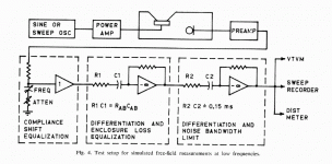
Actually, this just reminded of an AES article "Simplified Loudspeaker Measurements at Low Frequencies" in which far field pressure response is determined based on differentiating twice the pressure measured inside the enclosure.
AES E-Library Simplified Loudspeaker Measurements at Low Frequencies
Differentiating the internal pressure once gives response proportional to volume velocity of the cone.
Differentiating the volume velocity gives cone acceleration which is proportional far field pressure response.
See attached pic for Small's measurement setup.
The paper provides theory & measurement comparisons to show that this method works for both sealed AND vented enclosures.
Attachments
I am working on a low gain, large bandwidth feedback controller for a woofer. Passing Open Loop 0dB's at 30Hz and 450 Hz in order to have acceptable disturbance rejection of the harmonics in de 50-300 Hz area.
The gain is low, only 25dB max, but since it is wide, the rejection is not only in the sub 120Hz range, but in a wider range.
The gain is low, only 25dB max, but since it is wide, the rejection is not only in the sub 120Hz range, but in a wider range.
Attachments
Last edited:
This is certainly the case for a piston acting on a sealed system. For instance constant displacement of a woofer cone yields constant pressure inside the enclosure of a sealed box system.(as long as the frequency of interest has wavelength >> than enclosure dimension). But, radiated far field pressure response is proportional to cone acceleration not displacement.
Actually, this just reminded <me> of an AES article "Simplified Loudspeaker Measurements at Low Frequencies" in which far field pressure response is determined based on differentiating twice the pressure measured inside the enclosure.
AES E-Library Simplified Loudspeaker Measurements at Low Frequencies
Differentiating the internal pressure once gives response proportional to volume velocity of the cone.
Differentiating the volume velocity gives cone acceleration which is proportional far field pressure response.
See attached pic for Small's measurement setup.
The paper provides theory & measurement comparisons to show that this method works for both sealed AND vented enclosures.
I surely wish I had easy access to the AES Journal, as I did in the early 70s when I was following Richard Heyser's work. I will try to get the paper to study, as I'm always interested in learning. However, this appears to be all based on sinusiods or at best harmonically-related sinusoids. I still hesitate to believe it is this simple for complex non harmonically-related waveforms, i.e., most music.
However, this appears to be all based on sinusiods or at best harmonically-related sinusoids. I still hesitate to believe it is this simple for complex non harmonically-related waveforms, i.e., most music.
All complex wave forms can be built up from sinusoids.
How a system responds to transients, or sudden waveforms bursts is certainly relevant though.
MFB can improve a woofers transient response, but depending on the stability margins it may worsen response to transients and increase decay time even though steady state distortion is reduced. Somewhere I have seen published results for tone bursts tests on several well known MFB subwoofers. Some faired well, some not so much. I wished I could remember where I saw it...anybody remember this?
Topic shift...
In my previous response, I forgot to cover the topic of pressurization gain(aka room gain), which is one area in which constant pressure from constant displacement does come into play
The magnitude of acoustic pressure waves radiated from a woofer cone into free space or a large room is proportional to cone acceleration. But, what happens when the room starts to look small compared to the wavelength of the radiated sound? Well, the room will start to confine/contain the pressure rather than having the radiated waves bounce around it. Basically the room transitions from being a reflector of sound waves to a pressure vessel.
If your room was a perfectly solid, airtight, small concrete bunker, the measured SPL in the room would be proportional to woofer cone displacement for frequencies well below the lowest room mode. If you placed an ideal subwoofer (flat SPL response 1hz to 100Hz in free space) into this perfectly solid room, the measured response would be boosted by 12dB/oct below the lowest room mode. Most of our listening rooms are large enough and leaky/flexible enough that not much if any pressurization gain is seen.
But, if you happen to own a modern tightly sealed automobile, you can experience this gain for yourself. The 12dB/oct boost usually begins around 50hz for average sized cars. So, if you place a sealed subwoofer with f3 = 50Hz in the car(with windows rolled up of course), you will measure nearly flat SPL response down to 20Hz and below depending how airtight the vehicle is. This is because below 50Hz the -12dB/oct roll-off slope of the sealed subwoofer is equalized by the +12dB/oct pressurization gain.
An emphasis to add to Bolserst good post:
since at DIYaudio there are many faithful who believe that room gain magnifies bass loudness, it should be emphasized that is is wholly insignificant and with almost zero presence any place beside TIGHTLY sealed small cars made of steel (as Bolserst has already mentioned).
(There are other acoustic factors that may give you a delightful sense of bass boom - or bass absence - here and there in a room, but that isn't "room gain.")
Ben
Last edited:
Measurement of myth?
From: Investigating Room Gain, "How much boost is my subwoofer going to get?"
+30dB at 4Hz is a lot to gain from faith alone. 😛
Oh, it's nowhere near as much as some hope to be the case, as the page points out, but even in a quite large, lightly built room with small subs the measurements show it to be far from "insignificant" nor with "zero presence". It's just not so active higher up, but that may not be the case in a smaller room.
An externally hosted image should be here but it was not working when we last tested it.
From: Investigating Room Gain, "How much boost is my subwoofer going to get?"
+30dB at 4Hz is a lot to gain from faith alone. 😛
Oh, it's nowhere near as much as some hope to be the case, as the page points out, but even in a quite large, lightly built room with small subs the measurements show it to be far from "insignificant" nor with "zero presence". It's just not so active higher up, but that may not be the case in a smaller room.
Hi,
Anybody experimenting with CB subs will have noticed or measured this phenomen. It only requires the listening room to be ´closed´ up, as any open doorway to another room could function as a sytem of coupled caverns (Helmholtz resonator), thereby spoiling the effect.
The roomgain will come into effect only at lowest and infrasonic frequencies. The more obvious the smaller the room´s dimensions are.
This could be regarded as a reason of ´insignificance´, since there´s typically not much musical content in the lowest audible octave and due to the ear´s low sensitivity and the room´s structural prerequisites.
Still though the effect shouldn´t be neglected, especially not with subwoofer applications.
jauu
Calvin
Expressed in such a absolute manner the statement is grossly exaggerated to put it in a friendly way 🙄...it should be emphasized that is is wholly insignificant and with almost zero presence any place...
Anybody experimenting with CB subs will have noticed or measured this phenomen. It only requires the listening room to be ´closed´ up, as any open doorway to another room could function as a sytem of coupled caverns (Helmholtz resonator), thereby spoiling the effect.
The roomgain will come into effect only at lowest and infrasonic frequencies. The more obvious the smaller the room´s dimensions are.
This could be regarded as a reason of ´insignificance´, since there´s typically not much musical content in the lowest audible octave and due to the ear´s low sensitivity and the room´s structural prerequisites.
Still though the effect shouldn´t be neglected, especially not with subwoofer applications.
jauu
Calvin
Diogenes - despite the ambitions suggested by your name, I think it is deceptive to compare a woofer playing out in the yard with one playing in a concrete room and calling the difference "room gain" (as in your link). Lots of reasons the woofer is louder and "room gain" doesn't have to be one of them.
You have the possibility of "room gain" if you meet the following requirements:
1. walls, ceiling, and floor must be concrete (not cement block and certainly not drywall or plaster)
2. no door (OK... can be steel, but must be sealed all around when closed)
3. certainly no windows
4. radiators for heating (no HVAC ducts or A/C permitted)
5. your musical tastes are limited to sounds below 10 Hz.
If that characterizes your music room, the theoretical boost per octave is still small and only starting at some low frequency. Anyway, amp systems often have a way of shaping bass such as by cranking up the bass tone control a smidgen which might have the same effect.
Have I left out any other requirements? (Do the speakers have to be sealed boxes?)
You'll get better sound with good woofers and MF than with concrete walls and a steel door.
Ben
Last edited:
You are right, but the fact is that the signal from the accelerometer is exactly the same as the input signal. No need to integrate. When the input signal goes through zero, the speed of the cone is at maximum and the acceleration is zero. I should know, I have been looking at the signals on my scope for over 20 hours this week 🙂
I have no intentions of stealing this thread, but there have been questions about the correlation between "real" microphone output vs accelerometer measurements in this thread.
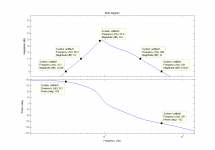
I have finished the initial testing of my "old fashioned" analogue MF system and have measurements from both accelerometer and microphone. The woofer is a Peerless XXLS 12" (830845) in a 135 liter box that weigh about 60kg.
The microphone was located about 1,5 inch from the woofer during the test. If located further away, the distortion goes up due to room reflections.
The numbers.
20Hz, 18,5V RMS on terminals, NO MF gives THD of 31,4% measured with accel
20Hz, 18,5V RMS on terminals, NO MF gives THD of 24,2% measured with mic
20Hz, 18,5V RMS on terminals, with MF gives THD of 1,34% measured with accel
20Hz, 18,5V RMS on terminals, with MF gives THD of 1,63% measured with mic
Here is a picture whre you can see the difference. (NOTE. The blue curve is inverted because the direction of the accel is positive inwards)
View attachment 359781
As you can see there is a sharper knee on the blue curve from the acceleremeter while the microphone curve is more smoothed out. I am not sure why this happens, but probably becuase the accelerometer is mounted just on top of the voice coil and can pick up higher frequencies than the whole cone transfer to the air.
PS. I was fooled by a poor measurement microphone for a long time. I was using a 300$ calibrated "Brand X" thinking it was good enough. But the distortion levels only came down to a certain level and stopped even when the accelerometer distortion went further down. I therefore built my own following Linkwitz guide with a Panasonic WM-61 capsule and a MAX427 opamp. With that the distortion levels matched.
Hello Amand,
Could you post an FFT spectrum of the subwoofers THD performance without motion (MF) feedback and with MF feedback, I think THD numbers do not give enough information and the magnitude of the frequency components that cause the distortion with and without MF feedback would be more informative.
Regards
Arthur
Diogenes - despite the ambitions suggested by your name, I think it is deceptive to compare a woofer playing out in the yard with one playing in a concrete room and calling the difference "room gain" (as in your link). Lots of reasons the woofer is louder and "room gain" doesn't have to be one of them.
The way I think about a loudspeaker in a room (LF region) has changed over the years from Room Gain to Boundary Reinforcement to Boundary Effects. Even the latter label may not be sufficiently descriptive. Suffice it to say, that environmental effects is a complex phenomenon. However, the idea of Boundary Reinforcement prevails, as the description closely follows the subjective change one observes when positioning a loudspeaker closer to or farther away from a room boundary. It is only when acoustic measurements are taken that the true nature of the effect can be appreciated (the dips and peaks are revealed).
Right! All kinds of acoustic effects along with a typically miniscule effect from "room gain."
Sadly, I suspect it is fair to say "most" are gremlins that cause trouble for us by being intractable as to location, frequency, or doubly sadly, not being amenable to feasible fixes (just have a look at the resonant absorber threads).
However, on the architectural front, there is much that can be addressed in the envelope and location of speakers. My favourite is heterogeneous woofers - as explored in detail in Toole's great book.
Ben
...As you can see there is a sharper knee on the blue curve from the acceleremeter while the microphone curve is more smoothed out. I am not sure why this happens, but probably becuase the accelerometer is mounted just on top of the voice coil and can pick up higher frequencies than the whole cone transfer to the air.
You might consider taking the captured accelerometer data(blue curve) and applying a full Hanning or Blackmann window and then perform an FFT on the windowed data. The resulting frequency response curve should let you know if the sharp knee you are seeing contains only frequencies that are harmonically related to the fundamental, or perhaps also some content related to a dust cap or cone break-up mode. I seem to recall that some of the XLS drivers did have a rather pronounced break-up mode. Where exactly did you attach the accelerometer? Middle of dust cap? At the dust cap/cone glue joint? Or did you remove the dust cap and get the accelerometer glue as close to the voice coil as possible.
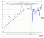
Measurement of myth?
Nice measurement set showing clearly the pressurization gain.
 Thanks for sharing.
Although the results in general look reasonable, I do wonder about their ground plane measurements for frequencies < 6Hz where the data deviates from the -12dB/oct response slope for a sealed woofer(Attachment #1). When calculating the delta to get the pressurization gain curve, this deviation is giving 7db-8dB more gain at 4Hz than it probably should. The resulting data would then fall more in line with other measurements I have seen and taken where the pressurization gain tapers off as you approach DC unless the room(or car) is perfectly sealed and very stiff. I wonder what type of door they had in their room? Most doors in US homes have a large gap under the door to help with air circulation for central air heating/cooling systems.
One other possibility for the deviation for frequencies <6Hz would be that their microphone response was not calibrated for frequencies that low. In that case, it would have affected the in-room measurements as well, and then the calculated deltas would be correct. But, I noticed that the website has data for a similar test performed in a large SUV.
Data-Bass
The ground plane measurements here do not show an abrupt change in slope below 6Hz so this seems to rule out the microphone calibration theory(Attachment #2). In any case you can clearly see the “in car” response is predominately flat down to 10 Hz even though the ground plane response of the woofer starts rolling off nearly 2 octaves above that. It would have been nice if they had included a pressurization gain curve calculated from the delta between the two measurement sets similar to what they did for the room. If I am reading the curves correctly, it would have shown the gain curve start to flatten from the 12dB/oct slope below 10Hz as air leaks and flexibility in the SUV started to affect its pressure containing capability.
Attachments
Last edited:
It is very helpful to have incisive discussions such as Bolserst provides above. But it is also helpful to summarize to help people who might have "irrational exuberance" about "room gain" based on a casual reading of his serious text.
In ordinary listening rooms, the effect of "room gain" north of 15 Hz stands somewhere between trivial and non-existent. But if your room is all concrete or your musical experience is in Jeeps with the windows rolled up and the ventilation ducts sealed shut*, you might be interested in implementing a bass-cut circuit.
Ben
*and you know the undocumented location of the pressure-relief system that operates when you slam the doors or run the A/C
Last edited:
Bolserst,
The particular measurement rig used for those measurements consisted of calibrated Earthworks M30 microphone & Quest SPL calibrator, Presonus Fire Studio interface, Powersoft K10 amplifier, etc...Anyway that signal chain is basically flat to the 8Hz region with the EW's M30 basically flat till about 5Hz, but the electronics do start to roll out sharply below 5Hz. The deviation from 12dB/octave below roughly 8Hz shown in the first graph is likely due to environmental noise contamination. Even with averaging it is quite difficult to obtain satisfactory SNR at such low frequencies in an outdoor groundplane environment for the baseline measurement with the inherent output limitations of typical devices. Being that the output is so low in level at such deep frequencies there is a high likelihood that background "drone" from heavy equipment, planes, cars, etc...is having effect. Such being the case the results below 10Hz should be considered "ballpark" with increasing deviation seen as the frequency drops and SNR worsens.
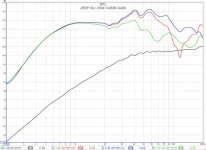
The room used was not sealed at all. The house was built in 1894 and this was a wood frame room over crawlspace with old duct work and a couple of large openings to other very large spaces. About as far from sealed as it gets. The Jeep was a standard model Grand Cherokee of 2004 vintage as driven every day that had a sealed enclosure placed in the cargo hold facing the back glass about 4" from the hatch. The measurements indicate what a single 90dB sensitive 4ohm woofer in a sealed enclosure driven by just 20 volts input can do in a medium sized SUV. Force multiplication at its finest.
Here is the data graph requested. Note that the second measurement labeled driver position is with the subwoofer cabinet rotated and firing towards the front instead of towards the rear so that the effect of orientation could also be compared.

The particular measurement rig used for those measurements consisted of calibrated Earthworks M30 microphone & Quest SPL calibrator, Presonus Fire Studio interface, Powersoft K10 amplifier, etc...Anyway that signal chain is basically flat to the 8Hz region with the EW's M30 basically flat till about 5Hz, but the electronics do start to roll out sharply below 5Hz. The deviation from 12dB/octave below roughly 8Hz shown in the first graph is likely due to environmental noise contamination. Even with averaging it is quite difficult to obtain satisfactory SNR at such low frequencies in an outdoor groundplane environment for the baseline measurement with the inherent output limitations of typical devices. Being that the output is so low in level at such deep frequencies there is a high likelihood that background "drone" from heavy equipment, planes, cars, etc...is having effect. Such being the case the results below 10Hz should be considered "ballpark" with increasing deviation seen as the frequency drops and SNR worsens.
The room used was not sealed at all. The house was built in 1894 and this was a wood frame room over crawlspace with old duct work and a couple of large openings to other very large spaces. About as far from sealed as it gets. The Jeep was a standard model Grand Cherokee of 2004 vintage as driven every day that had a sealed enclosure placed in the cargo hold facing the back glass about 4" from the hatch. The measurements indicate what a single 90dB sensitive 4ohm woofer in a sealed enclosure driven by just 20 volts input can do in a medium sized SUV. Force multiplication at its finest.
Here is the data graph requested. Note that the second measurement labeled driver position is with the subwoofer cabinet rotated and firing towards the front instead of towards the rear so that the effect of orientation could also be compared.
Last edited:
- Status
- Not open for further replies.
- Home
- Loudspeakers
- Subwoofers
- Low distortion, DSP based high gain servo controlled woofer controller.