juli@ and stxll have 2Vrms input sensitivity
x-fi usb hd max output level is little higher than 2Vrms (2.12Vrms)
viktor1k output (bellow 1vrms) -> julia/stx input
xfi -25dbfs output via 560k resistor -> viktor1k pcb ic2 pin6
x-fi usb hd max output level is little higher than 2Vrms (2.12Vrms)
viktor1k output (bellow 1vrms) -> julia/stx input
xfi -25dbfs output via 560k resistor -> viktor1k pcb ic2 pin6
Last edited:
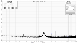
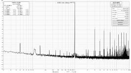
I repeated the test Low-distortion Audio-range Oscillator and intentionally chose high distorted ref clock - cheap ebay dsd generator.
pic1 - dsd gen distortion at 105mVrms, measured by Juli@
pic2 - viktor1k distorion at 750mVrms locked by gen from pic1, measured by Juli@
pic1 - dsd gen distortion at 105mVrms, measured by Juli@
pic2 - viktor1k distorion at 750mVrms locked by gen from pic1, measured by Juli@
Attachments
Last edited:
So something better than default? can be achieved without using one of the analyzer's generator output.
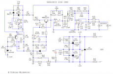
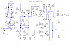
The latest schematics:
https://content21-foto.inbox.lv/albums/e/elterra/OscillatorNew/Gen1kHzN8.png
https://content21-foto.inbox.lv/albums/e/elterra/OscillatorNew/Gen10kHzN8.png
Simplest way for to get the 100Hz is to increase values of the 1kHz version capacitors C4, C6, C7, C11, C12, C16, C18 ten times. I recommend little different frequency instead of 100Hz for better separating the oscillator frequency harmonics from the power line voltage harmonics.
Vic.
Hello. I m about to finish a through hole prototype to use your sine wave oscillator for testing amps and preamps and i have some questions:
Can T1 (BC857C) be replaced with BC557C?
Can you suggest a TO-92 package jfet replacement for T2 (MMBF4391) ?
Any other DIP-8 package opamp to use for IC2 like OPA2134 , ΝΕ5532 or they will degrade performance?
Can BAS70 be replaced with BAT41?
Power supply is a +35V,Ground and not a dual rail +35V, -35V, Ground?
Attachments
Most questions are easy so I can answer instead of:Can T1 (BC857C) be replaced with BC557C?
Can you suggest a TO-92 package jfet replacement for T2 (MMBF4391) ?
Any other DIP-8 package opamp to use for IC2 like OPA2134 , ΝΕ5532 or they will degrade performance?
Can BAS70 be replaced with BAT41?
Power supply is a +35V,Ground and not a dual rail +35V, -35V, Ground?
1. Yes, BC857C and BC557C is almost the same transistor.
2. Don't know. Possibly, J111 (MMBF111)?
3. OPA2134 will definitely degrade performance a bit. I don't know why people like to use them. There are a lot of much better opamps, many of them cheaper or cost the same. NE5532 is so-so (I won't use).
4. BAT41 - yes.
5. Power supply is 35V total, definitely not +-35V.
Last edited:
Can T1 (BC857C) be replaced with BC557C?Hello. I m about to finish a through hole prototype to use your sine wave oscillator for testing amps and preamps and i have some questions:
Yes.
Can you suggest a TO-92 package jfet replacement for T2 (MMBF4391) ?
As Vovk Z suggest - J111
Any other DIP-8 package opamp to use for IC2 like OPA2134 , ΝΕ5532 or they will degrade performance?
LM4562 or LME49720, but must be tested for noise. Many of them have the "popcorn" noise.
Can BAS70 be replaced with BAT41?
Yes.
Power supply is a +35V,Ground and not a dual rail +35V, -35V, Ground?
35V DC must be single isolated (floating) supply.
Vic.
LM4562 or LME49720, but must be tested for noise. Many of them have the "popcorn" noise.
Vic.
What does popcorn noise look like in fft ?
I made a simple opamp oscillator with LME49720, signal passes 2 opamps, no amplitude stabilisation.
With 65mV voltage swing of first opamp, REW shows me a bit unstable THD 0.0001% to 0.0005%, coherent averaging, no notch.
According to datasheet curves its 0.005% for such low output voltage.
Will it be much better at 3V ?
I possibly can not go > 300mV, what can I do ? Force opamps into classA ?
You can see something here:
https://e2e.ti.com/support/audio/f/6/p/415907/2277275#pi320995=1
If you run your osc. with low signal, then you have higher noise effect. As result, may be bad stability. Also these opamps are sensitive to high frequency fields.
Why do you think, that the opamp not run in A class? Do you run it with a heavy load?
Thanks, it looks just like normal noise to me.
LME is classA ? But older NE5532 is not ? because sometimes suggested to tie a resistor to V- to force into classA.
From LME datasheet, THD is getting better with higher output voltage until peak at 3V, then worsens again.
Can you confirm this ?
LME is classA ? But older NE5532 is not ? because sometimes suggested to tie a resistor to V- to force into classA.
From LME datasheet, THD is getting better with higher output voltage until peak at 3V, then worsens again.
Can you confirm this ?

You can see something here:
https://e2e.ti.com/support/audio/f/6/p/415907/2277275#pi320995=1
If you run your osc. with low signal, then you have higher noise effect. As result, may be bad stability. Also these opamps are sensitive to high frequency fields.
Why do you think, that the opamp not run in A class? Do you run it with a heavy load?
I now suspect the OPA1656 does not have this 1 / f noise.
The external resistor to -may closes pnp transistor follower in output stage and extends class A region for npn follower in output stage. Otherwise by default both output transistors run with small quiescent current.Thanks, it looks just like normal noise to me.
LME is classA ? But older NE5532 is not ? because sometimes suggested to tie a resistor to V- to force into classA.
From LME datasheet, THD is getting better with higher output voltage until peak at 3V, then worsens again.
Can you confirm this ?
You see the THD+N in LME datasheet, not the THD, so the noise is the dominant at low signal levels. In analog schematics distortions typically always fall down at low signal levels.
Last edited:
The noise performance of the OPA1656 seems stable. Never saw the popcorn noise problems.I now suspect the OPA1656 does not have this 1 / f noise.
You see the THD+N in LME datasheet, not the THD,...
I was concerned that crossover distortion could compromise THD at low levels and overlooked the "+N".
Some datasheets suggest shielding and heatsinks.
'Class-A' output is for 'audiophile' devices (amps, preamps). This oscillator - is not audio device but it is measurement device. It doesn't need this. You do not need to change anything. This doesn't help (for many reasons). (Especially - if you are a newby).LME is classA ? But older NE5532 is not ? because sometimes suggested to tie a resistor to V- to force into classA.
Last edited:
Class A exists when the both output stage transistors (typically high side and low side transistors) have a collector current. As I mentioned, the output stage output runs with quiescent current. If the signal is small or load is light, the current difference thru transistors is also small, and output stage runs in A class. The transistors start run in AB class, when the load current exceed the output stage quiescent current.I was concerned that crossover distortion could compromise THD at low levels and overlooked the "+N".
Class A exists when the both output stage transistors (typically high side and low side transistors) have a collector current. As I mentioned, the output stage output runs with quiescent current. If the signal is small or load is light, the current difference thru transistors is also small, and output stage runs in A class. The transistors start run in AB class, when the load current exceed the output stage quiescent current.
Maybe there is a misunderstanding.
I should have written single ended classA.
To avoid the never perfectly matched N and P devices.
Just because in my oscillator the signal is small.
- Home
- Design & Build
- Equipment & Tools
- Low-distortion Audio-range Oscillator