From 4 yearrs ago here, the proof of concept-->
Using a 16 bit function gen to produce sine waves....
100hz with 150Hz LP filter.
Cleas it right up....
View attachment 861084
-B1B
Yes, it works, only question is the best implementation, finding a filter that has no distortion and no noise.
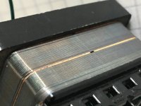
Now I made a 3.1 mH inductor, wound on a HQ audio transformer core incl. MU shielding.
With the coil inserted in the signal path after my 16 bit generator / simple bandpass filter, the distortion is equal to "no coil". See two screenshots.
However... Measured with my handheld Multimeter the coil Rs is near zero but with my RLC meter it is 10 ohms
I don´t understand. 1 layer with 0.8mm wire, about 20 windings.
If I put that inductor in my filter will it behave like a 10 ohms coil ???
Wild guesses here: What test frequency used by your meter? Might be much higher than 1kHz, perhaps skin skin effect and overstated? Losses magnetically coupled into shield? Such loss mechanisms would be real but not evident at DC.
1 kHz
My 3 mH aircoils are measured little over 1 ohm with the same RLC meter.
But these few windings translate to 10 ohms ???
In series with the signal, the transformer coil is ok, but in the filter, signal to ground there is very high distortion.
0,27% instead of 0,00022%
All windings revoved from audio transformer and new 20 windings.
Last edited:
Wrong iron material ?
The transformers only had 1 winding with 1 additional middle tap.
The transformers only had 1 winding with 1 additional middle tap.
Last edited:

My suspicion would be the core material. You could try removing the mu shield to determine if it's a contributor.
I think I know what is wrong
Transformer coils for speaker crossovers are open on one side.
Different magnetic flux something.
So I would have to cut every sheet of steel.
But then if one side is open, the MU shield will become a issue.
Or I try parallel windings to bring resistance down.
If that also will fix the distortion...
I'm a little confused on your measurements. First DMMs can get confused by the inductance measuring an inductor. The current source doesn't like bigger inductors.
Measuring with an LCR bridge you get the resistive component, some of which is the wire, some is losses in the magnetics. If you are making an inductor using transformer cores. it will saturate at a very low level if you put the iron back interleaved. You need an air gap to prevent the saturation. Usually the lams are all oriented the same way and a thin spacer is inserted between the E stack and the I stack, typically a very small gap (5/1000") is enough. Good transformer iron will saturate very easily.
The inductor won't show distortion until it passes current. Similar for caps. Putting the inductor in series with a high impedance input won't show anything. A source through the inductor to a low Z termination (600 Ohms) will show some. Gerhard's direction about a filter that has little current through the inductor at the target frequency is the right way to do it. You can analyze the current very well with LTspice.
I will get the details on the CLT inductors. I need some time to open it up again. I have other broken things to fix first.
Thanks, I rewound to 4 layers, restacked for gap and now have 3 mH at 0.5 ohms.
Still distortion that rises with level, can´t get better than 0,0022% which is the same as generator alone.
Checked the filter, it is on 1002 Hz.
Last chance is using a bigger core, this one is very small and overdriven easily.
Still distortion that rises with level, can´t get better than 0,0022% which is the same as generator alone.
Checked the filter, it is on 1002 Hz.
Last chance is using a bigger core, this one is very small and overdriven easily.
The transformer coil has the perfect shield against hum included. And Rs is better than any air coil.
Unfortunately with the bigger core there still is significant h3.
I could increase the filter impedance to reduce current but it will never be as good as the air coil.
Unfortunately with the bigger core there still is significant h3.
I could increase the filter impedance to reduce current but it will never be as good as the air coil.
Last edited:
Are you sure the H3 is from the inductor? Have you built a spice model and checked the current that would be going through the inductor at 1 KHz? I find doing this with spice can be humbling on the reality checks. Also if the distortion is from the inductor dropping the level will drop the distortion significantly.
Unfortunately with the bigger core there still is significant h3.
As I wrote: use it as a series circuit to short H3. No significant
current through it on H1 -> no additional distortion generated.
And the induced hum will be attenuated by the series cap.
Gerhard
Are you sure the H3 is from the inductor? Have you built a spice model and checked the current that would be going through the inductor at 1 KHz? I find doing this with spice can be humbling on the reality checks. Also if the distortion is from the inductor dropping the level will drop the distortion significantly.
Yes, I just put in the transformer coil and it had h3, changing back to air and h3 disappears. Both coils have 3.1mH, the air coil has 1.2 ohms, the transformer coil 0.2 ohms.
As I wrote: use it as a series circuit to short H3. No significant
current through it on H1 -> no additional distortion generated.
And the induced hum will be attenuated by the series cap.
Gerhard
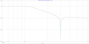
Yes, L current goes up at 1 kHz.
I tried simulation of LC in series and R to ground, again L current goes up at 1 kHz.
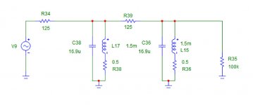
Also the notch will have series L and parallel/shunt L, so what choice I have ?
The original shunt filter circuit :
Attachments
Last edited:
I added the 3rd stage to my bandpass filter.
REW is stuck on 0,00022%
My R&S UPA3 now shows permanent THD underflow with short popups of -118 or -119dB which is a clear improvement over the 2 stage filter..
Is that 0,00022 the intrinsic distortion of my soundcard ?
Do I need get a better soundcard or built the notch ?
REW is stuck on 0,00022%
My R&S UPA3 now shows permanent THD underflow with short popups of -118 or -119dB which is a clear improvement over the 2 stage filter..
Is that 0,00022 the intrinsic distortion of my soundcard ?
Do I need get a better soundcard or built the notch ?

- Home
- Design & Build
- Equipment & Tools
- Low-distortion Audio-range Oscillator