I also looked at your sim of this. I see that the OL gain at 20k is ~90dB. With a 40dB CL gain, and -150dB distortion at 20k, that means the OL distortion is about -100dB at 20k. That is unbelieveable!
Jan
Jan
Jan, by now you should know that sims are far better amps than real circuits are. Still the preamp circuit should be very good. I would run it with +/- 24V or more. The higher rails do seem to help get lower distortion at a given level. The circuit has a lot of similarities to the Shibasoku amp and even more to the Panasonic circuit in their premium distortion analyzer.
Demian, I was not commenting on sim THD figures; I know these are pie in the sky.
It was the gain response I was interested in. That, coupled with the CL gain setting and CL distortion measurements, implied an OL THD at 20kHz of -100dB. That I find incredible.
Jan
It was the gain response I was interested in. That, coupled with the CL gain setting and CL distortion measurements, implied an OL THD at 20kHz of -100dB. That I find incredible.
Jan
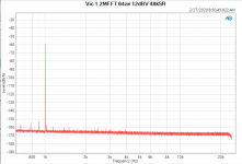
Pushing on, always pushing on! Read a paper about FFTs and realized the AP has more in it than I have used.
You get the lowest noise floor with the narrowest bin width. The narrower the bin, the less noise it receives.
Bin width = sample rate/(number of data points). So I set it to the lowest SR for 22k (48k), and max FFT length (1.2M). Higher output from the Vic (+12dBV, 4Vrms). And averaged 64x.
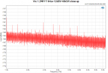
See below. Another 10dB down.
Finally, the close up hints at 2nd at -163dB and 3rd at -164dB. Wow!
Maybe I should do a 256 av but that will take at least an hour.
Jan.
You get the lowest noise floor with the narrowest bin width. The narrower the bin, the less noise it receives.
Bin width = sample rate/(number of data points). So I set it to the lowest SR for 22k (48k), and max FFT length (1.2M). Higher output from the Vic (+12dBV, 4Vrms). And averaged 64x.
See below. Another 10dB down.
Finally, the close up hints at 2nd at -163dB and 3rd at -164dB. Wow!
Maybe I should do a 256 av but that will take at least an hour.
Jan.
Attachments
Last edited:
Is the FFT locked somehow to the incoming fundamental?
If not, the obvious calculation:
48kHz, 1.2M FFT - takes 25s one calculation
64x averaging - takes 25 x 64 = 1600s = 26 minutes
Bin width: 0.04Hz
What is the chance for the fundamental/harmonics of a freewheeling analog oscillator to stay in the 0.04Hz bin for 26minutes?
But I may be completely wrong...
Smaller bins are certainly better, when you can get them. Just be mindful that your oscillator and adc have small enough drift to stay in a single bin or you'll need to account for the sidebands.
Pavel, Daniel, I understand what you are saying and have wondered about that. I have been pestering Viktor for a way to sync his oscillator to an external one, but that does not appear to be so easy.
Is there a way to verify if this does skew the measurements?
Jan
Is there a way to verify if this does skew the measurements?
Jan
Honestly, I do not think it is possible to sync a 1kHz analog oscillator to 0.04Hz precision for tens of minutes + keeping the ultra-low distortion at the same time.
IMO you would need to zoom the freq axis in to see individual bins adjacent to the fundamental/harmonic freqs (no idea if your tools offers such level of zoom, but e.g. exporting the FFT values to CSV would do).
Look at this discussion Average FFT Magnitude in bins - more averages of shorter FFTs with a bin large enough to cover your fluctuating frequency for the whole measurement period may be the way to go, IMO.
Jan -- also watch the type of window you use. There are lots of tradeoffs, but for this type of thing where you're chasing a moving target, you probably want a 'flat top' window. I don't know where to get it but Ron Potter wrote a comprehensive tome on the topic. I don't think it was ever published outside of (the old) HP.
Another technique that might be possible is to use 'order tracking' which is essentially a resampling algorithm used in rotating machinery analysis that follows the fundamental frequency of the signal and FFTs the resampled data. Several HP 'Dynamic Signal Analyzers' including the 35670A had this as a built-in feature or an option. I'm sure these days you could save all the data and do it in MATLAB.
Another technique that might be possible is to use 'order tracking' which is essentially a resampling algorithm used in rotating machinery analysis that follows the fundamental frequency of the signal and FFTs the resampled data. Several HP 'Dynamic Signal Analyzers' including the 35670A had this as a built-in feature or an option. I'm sure these days you could save all the data and do it in MATLAB.
I running a temperature sensitive test now which I need to finish. After that I will redo the Vic with say 1Hz bin width and many averages. See how that looks.
Jan
Jan
Jan -- also watch the type of window you use. There are lots of tradeoffs, but for this type of thing where you're chasing a moving target, you probably want a 'flat top' window. I don't know where to get it but Ron Potter wrote a comprehensive tome on the topic. I don't think it was ever published outside of (the old) HP.
Another technique that might be possible is to use 'order tracking' which is essentially a resampling algorithm used in rotating machinery analysis that follows the fundamental frequency of the signal and FFTs the resampled data. Several HP 'Dynamic Signal Analyzers' including the 35670A had this as a built-in feature or an option. I'm sure these days you could save all the data and do it in MATLAB.
I'm using AP's proprietary equiripple window. My 2722 at home has the option 're-align and move to bin center' , but not the 525 I am using here.
That may do what we need here as it is specifically meant for spectrum analysis in what AP calls 'open loop' meaning an external oscillator.
Jan
I wonder how averaging works for FFT results with different samplerate/length. If new samplerate calculation occurs only at the beginning, after a while the frequency will deviate anyway.
Jan, the link below contains an exhaustive treatment of spectral windows, including formulas for the calculation of their coefficients:
https://holometer.fnal.gov/GH_FFT.pdf
Regrads,
Braca
https://holometer.fnal.gov/GH_FFT.pdf
Regrads,
Braca
Yes this is a well known paper. Also, there is a whitepaper on the Virtins website with even more info including coefficients and spectral plots.
Jan
Jan
I did a lot of work trying to sync both Victors oscillator and the KH4400 using injection locking. Even starting with a low distortion source (Boonton 1120) I still got significantly more distortion out. Its been years and I'm up for trying again with fresh ideas. Otherwise you need something like what is internal to the Boonton for tuning and that is not a quick thing to do. But it works really well.
If I could lock the AP generator to the Vicnic, then I could lock the FFT to the AP generator. So far no luck.
Would a tuneable bandpass in the oscillator fb loop not force it to lock on to it? You only need a Hz or so tuning range.
Another idea I had was to get the quadrature of the master oscillator and use that to tune the slave oscillator, using its organic tuning system with the FET etc. The quadrature goes through zero phase very steeply. I use that in the tracking notch.
But as I said, my 2722 has a function to re-align (I think it actually re-samples) the FFT and move all spurs to bin center. That has to wait till I get home though.
Jan
Last edited:
I did a lot of work trying to sync both Victors oscillator and the KH4400 using injection locking. Even starting with a low distortion source (Boonton 1120) I still got significantly more distortion out.
I'm surprised at this, I would think there was a way to couple weakly enough to avoid an issue.
I used a transformer and a series cap into what I thought would be the optimum node but in retrospect maybe all i did was add harmonics. . . The transformer was to prevent unnecessary ground loops.
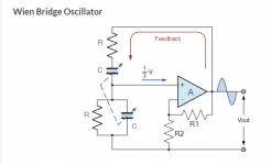
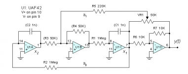
Attached are the simplest basic schematics I could find for both Wein Bridge and State Variable oscillators. What would be the best injection point?
Both the KH4400 and Victors are Wein Bridge oscillators. As I remember I tried injecting in the - input of the amp. It should take only a little to lock the oscillator if its close. I know that its really hard to prevent locking with crystal oscillators and special amps have been developed to improve input/output isolation.
Attachments
Attached are the simplest basic schematics I could find for both Wein Bridge and State Variable oscillators. What would be the best injection point?
I would look at injecting directly into the gain control element somehow. As I mentioned before I had an oscillator stabilized with a precision Tel-Labs PTAT resistor, it would only lock for a minute or so before thermal transients de-stabilized it, but when locked in the Q and THD were incredible. By Q I mean the noise sidebands, never saw anything like this.
In the tracking notch I put the filter quadrature output and the fundamental into a 1496 phase discriminator which then outputs a control voltage that is minimum when the notch is 'locked' to the fundamental. I can imagine that you could insert this control voltage into the oscillator control element to 'lock' it to the external source.
Jan
Jan
Attachments
In the tracking notch I put the filter quadrature output and the fundamental into a 1496 phase discriminator which then outputs a control voltage that is minimum when the notch is 'locked' to the fundamental. I can imagine that you could insert this control voltage into the oscillator control element to 'lock' it to the external source.
Jan
That would work with an analog multiplier on the quad loop back to tune the frequency, which is how Boonton does it. The digital side for the Boonton is more involved to tune to 5 digits with stability.
- Home
- Design & Build
- Equipment & Tools
- Low-distortion Audio-range Oscillator