How does it look inside?
Mostly empty. Two Vicnics against the front and a SilentSwitcher at the back.
Jan
Hi, Jan....the inverted output on the 5kHz is a bit higher in amplitude than the normal single ended input. On the 1kHz they are both the same amplitude. Do you have an explanation for that?
Jan
How big is the difference?
Probably the 10 pF cap in the inverter feedback produce the small phase shift at 5kHz, but the AGC increase the inverter signal for to get the properly level at Wien bridge output, where the AGC get the input signal. Also maybe the Wien bridge capacitors have a small difference (typically they are matched for app. 0,2%).
Hi Vic, I didn't measure it exactly but would guestimate about 10% higher level from the inverter than from the regular output.
Doesn't that imply that it actually is the output inverter that has gain < 1?
I have the schematic for the 1kHz oscillator; is the 5kHz the same (except of course the frequency determining parts)?
In itself I don't think the difference will be an issue but I was just curious.
Jan
Doesn't that imply that it actually is the output inverter that has gain < 1?
I have the schematic for the 1kHz oscillator; is the 5kHz the same (except of course the frequency determining parts)?
In itself I don't think the difference will be an issue but I was just curious.
Jan
I just measured my 20kHz example. I can't see any difference by the oscilloscope. The schematic is the same. Probably something went wrong in your case. The 10% difference is more too big. Please check the signal direct at the LME49720/LM4562 pins. If the frequency is right (typically the precision is better than +/-0.5%), then the difference from the main output (pin 1) and the inverter output (pin 7) must be negligible.
Would you please post the latest schematic?
Attachments

I just measured my 20kHz example. I can't see any difference by the oscilloscope. The schematic is the same. Probably something went wrong in your case. The 10% difference is more too big. Please check the signal direct at the LME49720/LM4562 pins. If the frequency is right (typically the precision is better than +/-0.5%), then the difference from the main output (pin 1) and the inverter output (pin 7) must be negligible.
I will check later or tomorrow. Today is a bad day at the lab - everything I touch seems to break instantly ...
Jan
> Today is a bad day at the lab - everything I touch seems to break instantly ...
Cheer up, Jan.
Tomorrow is a different day.
Patrick
Cheer up, Jan.
Tomorrow is a different day.
Patrick
Hi Vic, I didn't measure it exactly but would guestimate about 10% higher level from the inverter than from the regular output.
Doesn't that imply that it actually is the output inverter that has gain < 1?
I have the schematic for the 1kHz oscillator; is the 5kHz the same (except of course the frequency determining parts)?
In itself I don't think the difference will be an issue but I was just curious.
Jan
Vic, sorry, false alarm. I just measured again both phases of both oscillators and they are within 5mV of each other at 1V nominal output.
I must have been doing something stupid.
Jan
It was a very good day! Also measured my new HV regulator for Zout, at 315V and 100mA load.
Not superreg performance but not bad (and flat!) either! -74dB re: 600R is about 0.12 ohms.
Jan
Not superreg performance but not bad (and flat!) either! -74dB re: 600R is about 0.12 ohms.
Jan
Attachments
Last edited:
Jan do you remember my confession about blowing up $120.00 worth of parts because I assumed two different jfet models would have the same pin-out? That was a bad lab day.
Your response was "In the industry they call that R&D."
Your response was "In the industry they call that R&D."
😀
Yes similar happens to all of us one day or another. And once I even managed to insert 4 TO92's in a row with the same orientation, except that one was rotated on the board....
I now routinely check pinout once I receive the PCB. Takes a minute at most, can save a lot of aggravation (and $$).
Jan
Yes similar happens to all of us one day or another. And once I even managed to insert 4 TO92's in a row with the same orientation, except that one was rotated on the board....
I now routinely check pinout once I receive the PCB. Takes a minute at most, can save a lot of aggravation (and $$).
Jan
Jan,
would you please measure the oscillator with your AP and share the result? It would be interesting to know if the FET is as good as an LDR.
would you please measure the oscillator with your AP and share the result? It would be interesting to know if the FET is as good as an LDR.
Ralf, I have done that some time ago and I didn't see any difference with the GenMon test from AP, which is an internal loopback.
Levels were about -136dB for 2nd and -146dB for 3rd.
Jan
Levels were about -136dB for 2nd and -146dB for 3rd.
Jan
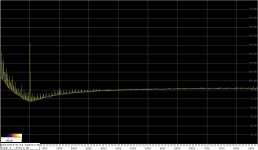
This is my take at measuring Victor's oscillator.
The measurement chain is Victor's (1Vrms out) -> massive-parallel buffer (8 X LM4562, 50 ohm output impedance) -> notch filter -> 60dB LNA -> audio interface.
The spectrum in the attachment shows the 2nd harmonic only at a level of -98dB w.r.t. 5Vrms (audio interface range). Correcting for the notch filter attenuation of 12dB@2kHz, and the LNA gain of 60dB, the 2nd is at -146dB w.r.t. 5Vrms, i.e. at -136dB w.r.t. 1Vrms.
Assuming now that the 3rd harmonic is just below the noise, i.e. at -103dB, and performing the calculation with the 3rd attenuation of 8dB in the filter, it would amount to -145dB w.r.t. 1Vrms.
Sorry about the mains interference, but it does not influence the above results.
Regards,
Braca
Attachments
Braca, that is interesting, it is pretty close what I measured, at least for the 3rd, but I thought I was measuring equipment residual. Are you sure you are not measuring the LM4562-buffer residual?
I really have to get my own notch going ...
Jan
I really have to get my own notch going ...
Jan
- Home
- Design & Build
- Equipment & Tools
- Low-distortion Audio-range Oscillator