guess you weren't paying close attention.
-150 wont get to it either. Need -160 noise floor.
I guess you can afford to hire a Maxwell demon. I know a few with reasonable hourly rates.
You will be attempting to 'accurately' read levels of Davids gen in the -145 area. I could retune the gen to my system and get lower but at 2-2.4v output of the gen, it will be in the mid 140's. I would allow at least 10dB margin for accuracy... so, -155 at least. But at -150 floor you might see something.
Ref 2.0v out, 1KHz; the THD+N is about -125 (400-30KHz)
-Richard
Ref 2.0v out, 1KHz; the THD+N is about -125 (400-30KHz)
-Richard
Last edited:
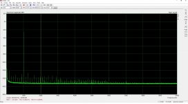
This is what I was able to get with the Asus Xonar Essence (single ended I/O), notched at 1022.46Hz. The notch depth is lower (only 70dB and change) compared to the original SA measurement (-87dB), since the Asus generator output impedance and the Asus input impedance are slightly de-tuning the TwinT.
Input signal level is -3dBFS (some 1.5Vrms), Y scale is in dBV, cursor is on the 3rd harmonic (the highest). See the ubiquitous multiple 1KHz artifacts discussed above. The noise grass is definitely much higher, nothing can be done to avoid this without balanced I/O hardware, which the Xonar essence sorely misses.
Don't know how to measure the M-Audio Audiophile 192 with balanced I/O with a single ended notch, it automatically converts to single ended, with the noise penalty.
Attachments

I think your notch is too deep. The converters non-linearity is greatest near the max and min levels. A more modest notch --- 40db (?) places it in the middle of the range for better accuracy.
And the spurious unwanted freq are excessive (IMO) and make it harder to see the data.
-RM
And the spurious unwanted freq are excessive (IMO) and make it harder to see the data.
-RM
guess you weren't paying close attention.
-150 wont get to it either. Need -160 noise floor.
THx-Richard
No you were not paying attention your scale factor was wrong, you made a mistake, no big deal. Waly must be channeling me again, listened to "Thee Psychick Sacrifice" just this morning. BTW the converters non-linearity does not matter when there is little or no fundamental.
Last edited:
I think your notch is too deep. The converters non-linearity is greatest near the max and min levels. A more modest notch --- 40db (?) places it in the middle of the range for better accuracy.
And the spurious unwanted freq are excessive (IMO) and make it harder to see the data.
TTYH, as usual.
Waly must be channeling me again.
I'm not a psychic psychick 😀.
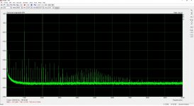
And finally, this is the best out of the Asus Xonar U7 MKII USB card. Remember, the owner replaced the original CS5861 ADC with the CS5381 flagship (it is pin to pin compatible) and this change pays for, in terms of performance (in particular when you got the CS5381 as a free sample 😀). The USB card is 2 meters away from the computer radiating the USB related 1KHz harmonics, these are largely gone.
0.0003% (-110dB) THD and 0.0083% (-81dB) THD+N, which is pretty good. However, and this is where the trouble starts, you have to keep the input signal very low (not more than 80mV) and the optimum input signal for getting these numbers is very small (50...80mV). This is in stark contrast with the Asus Xonar Essence and the M-Audio Audiophile 192 results shown before, where there is a rather wide optimum around 0dBV (-10...+3dB). I guess it's the price to pay for a USB powered (+5V) device. With the owner blessing, I may eventually try to replace the LME49726 rail to rail dual op amps (in MSOP packaging) if I can find a better suitable device (TI doesn't seem to have one).
The notched results are similar to the Asus Xonar Essence, but with much lower 1KHz harmonics and showing a dominant H2 (the Xonar and M-Audio had H3 dominant) likely this difference is due to the different opamps and much lower signal level.
I also tried to test a Creative E5 USB device and failed miserably. The Creative ASIO driver was crashing Arta, I tried the free RightMark but I got wildly different results, totally unstable, plus that the card settings in the $^%^# control/mixer software did not stick, they are moving around following an unknown logic, at the slightest adjustment (like changing the rates, etc...). So I find this card (otherwise quite expensive) not good at all for low level measurements.
Attachments
Last edited:
I'm not a psychic psychick 😀.
Cosey is more my style, I see the show closed today.
To avoid confusion, did you fix the scaling on those figures after David himself pointed out the 20dB (IIRC) discrepancy with the Shibasoku output? Waly is measuring a sound card BTW with its own noise and artifacts. Back of the envelope, a passive notch at an impedance level of 1k and in an noise BW of 1Hz should be able to resolve -150dB at the 2nd harmonic but not with 30dB of clearance from the noise floor. There are no Maxwell's demons.
Actually it was a 10db discrepancy depending on the input level. At 1Vrms input level there is no discrepancy. In level mode none for any range.
Point is we all need to test for error before conducting a measurement and not be complacent about it. There is a lot to go wrong.
Actually it was a 10db discrepancy depending on the input level. At 1Vrms input level there is no discrepancy. In level mode none for any range.
Point is we all need to test for error before conducting a measurement and not be complacent about it. There is a lot to go wrong.
Sorry I didn't go back and look, the fact is there is nothing about a Shibasoku or AP that can remove the noise from the basic components in the signal path. Be it a passive or active notch filter, for instance, the Shibasoku has 3k source resistance at the input, presenting a plot with 2nV of noise is simply wrong. These simple sanity checks should be instinctual.
and if you were listening, I said you needed to add the correction factor mentally. But, I also use one volt Fs scale and reduce the gen output via a voltage divider at the 725D's input which places a 1K in parallel with the input.
-RM
-RM
addendum to above -- David's gen reduced to 1 v output:
No correction needed, then.

-RM
No correction needed, then.
-RM
Last edited:
Slightly OT: Just got the papers program for the next AES convention. It's now getting to the point that I don't even understand the titel of papers:
'Joint Parameter Optimization of Differentiated Discretization Schemes for Electronic Audio Circuits'.
I'm really getting old....
Jan
'Joint Parameter Optimization of Differentiated Discretization Schemes for Electronic Audio Circuits'.
I'm really getting old....
Jan
yes, some of the articles are like this gen or analyzer.... details of details of details and more sub-details of those.
-RM
-RM
addendum to above -- David's gen reduced to 1 v output:
No correction needed, then.
View attachment 607132
-RM
It seems some, like scott and waley, didn't pay attention that I had readjusted the output from David's 'factory' setting and trimmed it for lower distortion. So, as stated, my gen was out = .9v and was of course using the 1v scale of the analyzer. The above shown setup is with gen back up to 2+ v out but atten to one volt so I can still use the same 1 v scale and compare distortion levels .9v vs 2.x volts.
-RM
Last edited:
For all this THD comparison stuff it would be helpful to settle on a specific input
voltage, say 1 Vrms.
-10 dBu or less is too easy and not very realistic.
The results of the FFT readings depend on the length (ENBW, effective noise bandwidth) and on the weighting filter.
So this should be corrected for: ENBW = 1 Hertz,
and weighting filter correction applied (or at least specified).
A Excel Table would be helpful too.
To me it is interesting that no manufacturer specifies more that
105 dB THD+N for anaylzers based on the ADC/DAC approach.
For all this THD comparison stuff it would be helpful to settle on a specific input
voltage, say 1 Vrms.
-10 dBu or less is too easy and not very realistic.
The results of the FFT readings depend on the length (ENBW, effective noise bandwidth) and on the weighting filter.
So this should be corrected for: ENBW = 1 Hertz,
and weighting filter correction applied (or at least specified).
A Excel Table would be helpful too.
To me it is interesting that no manufacturer specifies more that
105 dB THD+N for anaylzers based on the ADC/DAC approach.
I was just looking at the AP stuff. The 515 specced at -102dB costs $ 7k. The top of the line 555 that boasts -117dB cost $ 28k...
I wonder what converters are used in these units - anybody know?
Jan
addendum to above -- David's gen reduced to 1 v output:
No correction needed, then.
View attachment 607132
Nice setup to measure sub uV signals 😉. BTW, any resistor in parallel to the input won't change the series 3k resistor noise.
To me it is interesting that no manufacturer specifies more that
105 dB THD+N for anaylzers based on the ADC/DAC approach.
If the caps in the switched cap stuff are too small you simply have KT/C noise on top of the quantization noise. This is often the case along with the voltage noise of the CMOS amps being the floor not the 24 bit quantization noise.
BTW Dave what is your oscillator topology (SVO?) and what are the resistor and cap values at 1kHz. It should be trivial to simulate the noise floor as I did for the simple Wein bridge. There's nothing special about building an oscillator that does anything to change the amplitude relationship of the output to the noise.
Last edited:
- Home
- Design & Build
- Equipment & Tools
- Low-distortion Audio-range Oscillator