may not be falling of a log easy, but for a composite op amp circuit it looks quite possible with today's better op amps
like 400 mA, 100 MHz CFA DSL drivers in multi Watt Pdiss PowerPad packages
in inverting gain in particular it is just compensating the loop(s) with a low noise input op amp wrapping its gain around a CFA designed to drive DSL a few W into 25 Ohms primary of the line matching xfmers
TPA6120 CFA (rebranded THS6015) was my choice, I've paralleled pairs' outputs, biased them into push-pull Class A
with a OPA627 as input op amp wrapping the paralleled TPA6120, it measured > 120 loop gain to 30 kHz in hardware (well there was one more op amp adding loop gain too - that makes the compensation much more interesting)
some info a few pages around:
http://www.diyaudio.com/forums/equi...n-audio-range-oscillator-368.html#post3938612
I see. So spice tends to inflate the gain prediction.
The TPA6120 is pretty good but you need at least 30 dB distortion reduction from its native performance. That's a tall order even though its bandwidth makes stabilizing easier if you don't need ultrawide bandwidth. These are measurements I made from the TI demo board a few years ago.
There are two other candidates for this- the LME49600 (That Jens is using in his interface) and the OPA1622. AD may have some candidates I'm not aware of as well. The LME49600 would be the easiest since its targeted at this application. I have the TI demo board for it somewhere but have not measured it. I just got the demo board for the OPA1622 as well. I'm looking at the OPA 1622 as an upgrade in the KH4400. That will not be simple.
Still -150 dB distortion into 50 Ohms is a major undertaking.
Attachments
I thought of this when looking over the Boonton schematics and how easy it would be to have them track
with computer control and both having the same tuning elements. They could even have similar PCB layouts
for the SV osc, LP, and notch. Did you consider gain error introduced by the LP filter? Not sure what I'd do
about that.
Did you have a look at the osc gain control in the Boonton by any chance?
For level control, I would probably connect the oscillator's agc input to the output of the LPF; if doing that interfered too much with stability, I would use a two-loop approach, with the oscillator having its own usual agc loop and then with a detector at the output of the LPF to just tweak the level-setting threshold of the oscillator's main loop. Very little tweaking would be needed if the LPF tracked the oscillator frequency even with a reasonable approximation.
No, I did not take a look at the Boonton circuit.
Cheers,
Bob
comment...... not sure why driving 50 ohms is part of the requirement.... seems too low and not needed (?). Most oscillators produce far more voltage than needed for testing DUT. So, atten and a buffer could work and with huge fb amount a buffer would have distortion products into the noise. If an analog LP filter is used, it might be the buffer also as many filter typologies use a buffer configured opamp. Maybe an LT1468.
THx-RNMarsh
THx-RNMarsh
Last edited:
I'm thinking if we use actives we'll just get the distortion of the amplifier.
I think that the underlying presumption is that the distortion of the amplifiers used in the SVO is lower than the distortion introduced by the agc control element (e.g., JFET) and/or the agc control signal. I don't think one can make an oscillator with lower distortion than that of its amplifiers. By extension, the active filter would be built from the same finest available op amps. Of course, those op amps might add some distortion to that created by the op amps in the oscillator.
And then, of course, we still have the distortion added by the output amplifier in either case.
Perhaps the quickest way to answer this question is to build a fixed frequency 1kHz SVO and follow it with a fixed-frequency SVF accurately tuned to the same 1kHz. Then look at the distortion at the output of the oscillator compared to that at the output of the SVF.
Cheers,
Bob
comment...... not sure why driving 50 ohms is part of the requirement.... seems too low and not needed (?). Most oscillators produce far more voltage than needed for testing DUT. So, atten and a buffer could work and with huge fb amount a buffer would have distortion products into the noise. If an analog LP filter is used, it might be the buffer also as many filter typologies use a buffer configured opamp. Maybe an LT1468.
THx-RNMarsh
The input circuits of as number of products including both audio amps and test equipment actually generate distortion. A 50 Ohm source allows you to overcome the input nonlinearities. Adding series resistance is easy but negative resistors are troublesome.
Also 600 Ohms as a source dictates a minimum noise floor (440 nV/20K or 3.1 nV/rtHz). 50 Ohms reduces that by about 20 dB. Its a limit I do encounter with the 600 Ohm sources.
For level control, I would probably connect the oscillator's agc input to the output of the LPF; if doing that interfered too much with stability, I would use a two-loop approach, with the oscillator having its own usual agc loop and then with a detector at the output of the LPF to just tweak the level-setting threshold of the oscillator's main loop. Very little tweaking would be needed if the LPF tracked the oscillator frequency even with a reasonable approximation.
No, I did not take a look at the Boonton circuit.
Cheers,
Bob
The Boonton uses a classic sample and hold AGC + analog multiplier. Straightforward but complex and expensive to implement. Especially since sample and hold chips are becoming obsolete. Davida's used of an ADC + DAC for that is really a good idea and simpler. Possibly cheaper. it also has a network of clamp diodes to speed up settling that works really well.
The ADC and Mdac I used are very expensive. They have all the glue circuitry added in.
This could be done with a great deal less expense but the glue logic and analog front end would have to added.
The ADC I use can withstand +/- 25V absolute maximum and the Mdac +/-18V at the reference input.
Microchip has some possible candidates and really cheap too.
This could be done with a great deal less expense but the glue logic and analog front end would have to added.
The ADC I use can withstand +/- 25V absolute maximum and the Mdac +/-18V at the reference input.
Microchip has some possible candidates and really cheap too.
If the ADC can be triggered asynchronously then it does solve a handful of problems. A 12 bit ADC may be good enough. Next question- would a digipot work as an AGC element? Also would it work for the R component of the tuning? http://www.analog.com/media/en/news...ection-guide/Choosing_the_Correct_Digipot.pdf Would the residual non-linearity limit the performance? Is there a work around?
If the ADC can be triggered asynchronously then it does solve a handful of problems. A 12 bit ADC may be good enough. Next question- would a digipot work as an AGC element? Also would it work for the R component of the tuning? http://www.analog.com/media/en/news...ection-guide/Choosing_the_Correct_Digipot.pdf Would the residual non-linearity limit the performance? Is there a work around?
I think the distortion is kind of high and they are slow.
The 14bit Mdac is less expensive and probably enough resolution.
I was looking at the energy measurement AFEs from Microchip. Two 24bit ADC capable of measuring instantaneous power. It's a $3.00 item. But I don't think there is any control over the sample triggering. Not asynchronous.
Last edited:
The input circuits of as number of products including both audio amps and test equipment actually generate distortion. A 50 Ohm source allows you to overcome the input nonlinearities. Adding series resistance is easy but negative resistors are troublesome.
Also 600 Ohms as a source dictates a minimum noise floor (440 nV/20K or 3.1 nV/rtHz). 50 Ohms reduces that by about 20 dB. Its a limit I do encounter with the 600 Ohm sources.
Hi Demian,
I think that would be a reduction of 10 dB in going from 600 ohms to 50 ohms, since noise voltage goes as the square root of resistance.
Cheers,
Bob
So maybe something between 50 - 600 ohm load is OK as trade-of between distortion and noise.
THx-RNMarsh
THx-RNMarsh
I don't know what I was thinking as there seem to be plenty of these boxes.
Here is what was recommend to me.
"I would go with SymNet if I were refabbing the speakers and using separate amps/XOV. At the current used prices, they are a almost a giveaway. These boxes were designed by the engineers at Lucid, a company that made some of the best digital audio mastering electronics available. Symetrix bought Lucid for their digital audio chops. I used SymNet boxes in many studios and high-end Home Theaters I designed. 8 outputs leaves you the ability to incorporate Bass Management and EQ for a Subwoofer output, if desired."
One box solves a lot of problems.
The first is there are plenty of components and parts for them.
Along with a robust website too.
So for a reasonable amount buying a used symnet express or cobra
4x8 (four by eight) that gets you four analog inputs and eight analog
outputs.
The other nice thing is once you open up the box...you'll find its designed
nice and broadly laid out, easy to work on with a bunch of stuff in there I don't
understand.
I'm sure with Demian's lock in method you can have some nice digital inputs
and out puts along with a lot of control for what ever you wanted to do.
With the software control capabilities it's will be a good tool for dual tone
output generator, bursts, or whatever mix we can dream up.
I don't know how this fits in with the EMU stuff. I bought one of the 1616 units and as I recall I had the same challenges as Demian getting the thing apart, and trying to finagle it back together again.
Demian or Richard, there are a number of the units I see for sale in The City.
check them out on fleabay. Also here is a link to their website.
I talked with them and their helpful people. This isn't a consumer junk company. The physicist/acoustician recommended it to me because as I ended up with his original Mastering Studio Speakers that he just couldn't toss out. Sadly, I'm in the process of doing the reserection on them and will end up tri-amping them.
Downloads - Symetrix
From there you can scroll down until you see the
Symnet Designer 10.07 software download.
If you don't have a box, just open it up
and look around.
Here is the main page:
Home - Symetrix
SPL Computer in Composer Link:
http://www.symetrix.co/support/downloads/
These are really Maker Space type boxes for professional tinkerers.
And check out the friendly resources.
I'm thinking of using one of these as the front end for any manner of
instruments, for a DSP Function generator
OR
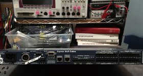
I'll post some pics...inside is like a cross between a Panasonic & ShibaSoku.
AND
It has those little connector sticks sticking up that we can affix gator clips
to easily and get into all kinds of trouble.
Maybe it will give someone and idea and save on some hacking around.
The symnet express box has four analog inputs and 8 analog outputs.
Cheers,
Sync
Here is what was recommend to me.
"I would go with SymNet if I were refabbing the speakers and using separate amps/XOV. At the current used prices, they are a almost a giveaway. These boxes were designed by the engineers at Lucid, a company that made some of the best digital audio mastering electronics available. Symetrix bought Lucid for their digital audio chops. I used SymNet boxes in many studios and high-end Home Theaters I designed. 8 outputs leaves you the ability to incorporate Bass Management and EQ for a Subwoofer output, if desired."
One box solves a lot of problems.
The first is there are plenty of components and parts for them.
Along with a robust website too.
So for a reasonable amount buying a used symnet express or cobra
4x8 (four by eight) that gets you four analog inputs and eight analog
outputs.
The other nice thing is once you open up the box...you'll find its designed
nice and broadly laid out, easy to work on with a bunch of stuff in there I don't
understand.
I'm sure with Demian's lock in method you can have some nice digital inputs
and out puts along with a lot of control for what ever you wanted to do.
With the software control capabilities it's will be a good tool for dual tone
output generator, bursts, or whatever mix we can dream up.
I don't know how this fits in with the EMU stuff. I bought one of the 1616 units and as I recall I had the same challenges as Demian getting the thing apart, and trying to finagle it back together again.
Demian or Richard, there are a number of the units I see for sale in The City.
check them out on fleabay. Also here is a link to their website.
I talked with them and their helpful people. This isn't a consumer junk company. The physicist/acoustician recommended it to me because as I ended up with his original Mastering Studio Speakers that he just couldn't toss out. Sadly, I'm in the process of doing the reserection on them and will end up tri-amping them.
Downloads - Symetrix
From there you can scroll down until you see the
Symnet Designer 10.07 software download.
If you don't have a box, just open it up
and look around.
Here is the main page:
Home - Symetrix
SPL Computer in Composer Link:
http://www.symetrix.co/support/downloads/
These are really Maker Space type boxes for professional tinkerers.
And check out the friendly resources.
I'm thinking of using one of these as the front end for any manner of
instruments, for a DSP Function generator
OR
I'll post some pics...inside is like a cross between a Panasonic & ShibaSoku.
AND
It has those little connector sticks sticking up that we can affix gator clips
to easily and get into all kinds of trouble.
Maybe it will give someone and idea and save on some hacking around.
The symnet express box has four analog inputs and 8 analog outputs.
Cheers,
Sync
Last edited:
Okay,
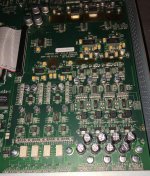
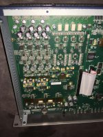
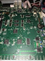
I took it apart, I had to remove 8 screws to get to the board.
Not to shabby really. And there are multiple network types
available.
Pics are attached they are large so y'all can zoom in.
Demian, check it out, no folding the cards over eachother
and snapping them together.
I've got the software on the other two computers. I really
need to make a dedicated bench computer with a large
server with RAID. It looks to have some good chip stock.
the SHARC are supposed to be top shelf yes?
You guys tell me?
Heck, I got a schematic for it too, somewhere.
So for a couple of C-notes, on a good used piece
of gear. Free software downloads and a bunch
of support. I'm trying to think out of the box.
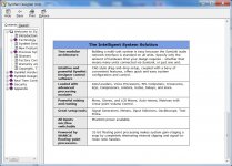
Look at the system solutions...I think any of these
boxes has a signal generator, meters, Oscilloscope, and
test probes all in it. (it may be virtual).
Okay, it's back to home work for me.
Let's see PN Diode,
P-type positive, arrow side, holes, majority/minority contributors
N-type negative, bar side, electrons. majority/minority contributors
tri-valent or penta-valent Si doping.
antimoniy or boron.
Cheers,
Sync
I took it apart, I had to remove 8 screws to get to the board.
Not to shabby really. And there are multiple network types
available.
Pics are attached they are large so y'all can zoom in.
Demian, check it out, no folding the cards over eachother
and snapping them together.
I've got the software on the other two computers. I really
need to make a dedicated bench computer with a large
server with RAID. It looks to have some good chip stock.
the SHARC are supposed to be top shelf yes?
You guys tell me?
Heck, I got a schematic for it too, somewhere.
So for a couple of C-notes, on a good used piece
of gear. Free software downloads and a bunch
of support. I'm trying to think out of the box.
Look at the system solutions...I think any of these
boxes has a signal generator, meters, Oscilloscope, and
test probes all in it. (it may be virtual).
Okay, it's back to home work for me.
Let's see PN Diode,
P-type positive, arrow side, holes, majority/minority contributors
N-type negative, bar side, electrons. majority/minority contributors
tri-valent or penta-valent Si doping.
antimoniy or boron.
Cheers,
Sync
Attachments

Last edited:
I like simple solutions ----
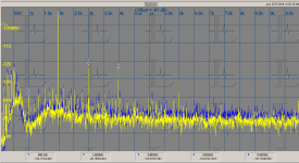
Here is a GP generator set to 100Hz and -10dBv. A General Purpose gen.;
The filtering is shown set for 2KHz and 1KHz and 150Hz. You can see the harmonics/noise dissappear beyond the filter setting.


Now all we need to do is find a way to sync a variable LP filter with the variable freq ultra low thd generator. Voila ! No harmonics.
THx-RNMarsh
Here is a GP generator set to 100Hz and -10dBv. A General Purpose gen.;
The filtering is shown set for 2KHz and 1KHz and 150Hz. You can see the harmonics/noise dissappear beyond the filter setting.
Now all we need to do is find a way to sync a variable LP filter with the variable freq ultra low thd generator. Voila ! No harmonics.
THx-RNMarsh
Last edited:
YES - just a proof of concept with real tests -- not SIM -- that a filtered output can be a very effective solution to the quest of zero (noise limited) distortion gen/source.
-RNM
-RNM
The reason I asked is that it seems to imply that a miniDSP is clean down to, what, -130dB? That's not expected.
Jan
Jan
The reason I asked is that it seems to imply that a miniDSP is clean down to, what, -130dB? That's not expected.
Jan
Not a chance, neither the A/D or the D/A support much over -100dB at best. It's irrelevant how good the math is.
So how to interprete the last shot in #5975 then? I also find it very hard to swallow. I mean, wouldn't the filter itself generate appreciable distortion? Where is it?
Jan
Jan
- Home
- Design & Build
- Equipment & Tools
- Low-distortion Audio-range Oscillator