Ah! so that's what I do.
Ok, tried that. I got a really ugly looking oscillation. I ran it for both 10 and 20 seconds. Sump'in ain't right.
With my oscillator sims I run them for minutes.
David.
Ok it runs in LTSpice. Injecting 50 cycles of 1KHz at 1uA into pin 6 of IC2b gets it running within 1 second at 10V p-p. After 2 secs the AGC starts to get the level down to about 4V p-p after 5 secs.
It starts up more smoothly if you can skip the initial DC operating point solve at the start. That will allow C2 to charge up normally allowing the AGC loop to start up as designed
I used this Phillips PMBF4391 model
.MODEL PMBF4391 NJF(VTO=-8.0337E+000 BETA=1.56450E-003
+ LAMBDA=1.00000E-002 RD=8.25115E-001 RS=8.25115E-001
+ IS=6.54620E-016 CGS=8.25000E-012 CGD=1.32500E-011
+ PB=7.72344E-001 FC=5.00000E-001)
Ok it runs in LTSpice. Injecting 50 cycles of 1KHz at 1uA into pin 6 of IC2b gets it running within 1 second at 10V p-p. After 2 secs the AGC starts to get the level down to about 4V p-p after 5 secs.
It starts up more smoothly if you can skip the initial DC operating point solve at the start. That will allow C2 to charge up normally allowing the AGC loop to start up as designed
I used this Phillips PMBF4391 model
.MODEL PMBF4391 NJF(VTO=-8.0337E+000 BETA=1.56450E-003
+ LAMBDA=1.00000E-002 RD=8.25115E-001 RS=8.25115E-001
+ IS=6.54620E-016 CGS=8.25000E-012 CGD=1.32500E-011
+ PB=7.72344E-001 FC=5.00000E-001)
Thanks! I will get to this tomorrow hopefully.
I used your model, but I still can't get it to work. I think I just don't know enough about using my software.
I used your model, but I still can't get it to work. I think I just don't know enough about using my software.
It wouln't hurt to download LTspice and try it. It's free.
I have used a single 1us 10V pulse though a 1 Meg resistor somewhere into the input of the multiplier just to get them going.
David.
Last edited:
I have used a single 1us 10V pulse though a 1 Meg resistor somewhere into the input of the multiplier just to get them going.
Yes, they don't need much. In fact, this one will start by itself if the initial DC operating point solve is skipped. With other designs, I've found that forcing them with a few cycles at their operating frequency and at the right level gets them started and stabilised quicker. This one seems less responsive to such treatment.
So, I have some good news anyway. I lashed up a LME49720 in a mixed feedback arrangement with a Jensen 112-LCF output transformer (not their best output transformer by far) and got this result. I think it's pretty good. On the bench, bandwidth was really great. It's running on 2x9V batteries.
Attachments
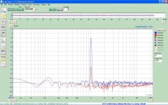
So, I have some good news anyway. I lashed up a LME49720 in a mixed feedback arrangement with a Jensen 112-LCF output transformer (not their best output transformer by far) and got this result. I think it's pretty good. On the bench, bandwidth was really great. It's running on 2x9V batteries.
Are you using the feedback technique in there app note?
It look like it needs some trimming.
David.
Yes, they don't need much. In fact, this one will start by itself if the initial DC operating point solve is skipped. With other designs, I've found that forcing them with a few cycles at their operating frequency and at the right level gets them started and stabilised quicker. This one seems less responsive to such treatment.
I wonder if the right kind-amount of stimulus other than feeding the signal back could be done. Kind of like flicking a tuning fork.
David.
Are you using the feedback technique in there app note?
It look like it needs some trimming.
David.
It's from Lundahl's application note.
Trimming in what way? I don't see any distortion above the noise floor.
It's from Lundahl's application note.
Trimming in what way? I don't see any distortion above the noise floor.
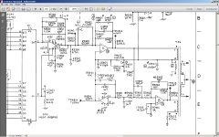
Well get the noise down. AP used this in the SYS1 with outstanding results.
The op amps are discrete of their design. They look more like small power amps.
David.
Attachments
Last edited:
Oh, the noise is from the inexpensive Behringer ADC/DAC that I'm using. Thanks for posting the AP schematics.
This is basically what I did, except for the different op amps. Let me study those AP schematics and see if there some even more improvements that can be made. I followed the equations in the Lundahl note:
http://www.lundahl.se/pdfovrigt/feedbck.pdf
http://www.lundahl.se/pdfovrigt/feedbck.pdf
Attachments
Well get the noise down. AP used this in the SYS1 with outstanding results.
The op amps are discrete of their design. They look more like small power amps.
David.
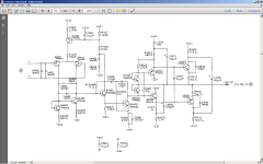
I can see why the op amp "A" would have to be powerful, since it is driving op amp "B" with a 1.0 kohm input impedance in parallel with the transformer load and the (1.0 + 1.0)kohm feedback resistors. The op amp "B" has to drive a (1.0 + 1.0)kohm feedback resistors in addition to the transformer load. I remember reading about the temperature compensation winding 2 (xfr connections 3 + 4) to reduce distortion even further. They also added a servo U431A. (Why do designers put 2x1.0 kohm resistors in series when a perfectly good 2.0kohm resistor is available?)
Since I'm only interested in 1kHz performance, I probably don't need a lot of extra do dads.
Last edited:
This is the amplifier section for A and B.
David.
I guess they wanted something that could swing a lot of volts into a lower load?
(Why do designers put 2x1.0 kohm resistors in series when a perfectly good 2.0kohm resistor is available?)
Cheaper by the dozen I guess. Maybe this was the manufactures idea.
David.
Last edited:
Cheaper by the dozen I guess. Maybe this was the manufactures idea.
David.
Maybe they paid a ton of money for a "special" 1 kohm resistor?
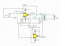
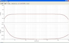
Here's the simulated Bode plot for the above circuit. Obviously, I don't need response to subterranean levels, but I did want no phase shift around 1kHz. For general purpose use, the coupling capacitors could be increased in size to get the lower frequency cut off down to 1Hz or so. As it is, it appears to be fine for both 1kHz and 10kHz oscillators. Also, since there is no funny resonant peak in the HF response, then no compensation capacitor in the feedback loop is required.
Attachments
- Home
- Design & Build
- Equipment & Tools
- Low-distortion Audio-range Oscillator