Have you tried it? Even with several percent amplitude mismatch output ripple is likely still much lower than for an average or RMS detector (with the same filtering). And you can easily trim the amplitude match for each range.
The S & H peak detector is cleary better, but also more difficult to implement right.
Samuel
I have a pair of AD RMS detectors coming from Scott. The output ripple from these IC's is the square of the input. If I use one on the output and one on a quadrature output I can sum the two together and null the ripple. This can be done with the currents before filtering so no
summing amplifier is required, then follow it with the internal buffer(s). This should be interesting to try.
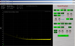
This is the output of the RMS detector for the auto set level in the 339A.
1KHz input at 1Vrms and 1Vdc output.
I can live with this but it not as good at lower frequencies.
This can be corrected with more filtering.
1KHz input at 1Vrms and 1Vdc output.
I can live with this but it not as good at lower frequencies.
This can be corrected with more filtering.
Attachments
Last edited:
Lets do more filtering first and see what happens. Thx-RNM
Sure. But with two of these I can really go to town.

OK just confirmed that the cap is necessary with the photovoltaic/JFET method and was able to trim the seconds into the noise with it (.033uF). I am using a bridge technique comparing a perfect resistor attenuator to one with the FET. I'm nulling a J310 against 100 Ohms with about .5V p-p across the FET (I assume this is too much). What are good numbers to take a measurement at?
OK just confirmed that the cap is necessary with the photovoltaic/JFET method and was able to trim the seconds into the noise with it (.033uF). I am using a bridge technique comparing a perfect resistor attenuator to one with the FET. I'm nulling a J310 against 100 Ohms with about .5V p-p across the FET (I assume this is too much). What are good numbers to take a measurement at?
Hi Scott,
The 339A Jfet has about 50mVpp Vds.
davada -- pls give source and make/model/part number info for that level control pot (10K) you replaced -- repaired. Mine has some worn spots in it that cause thd to rise when you hit them. Thx-RNM
davada -- pls give source and make/model/part number info for that level control pot (10K) you replaced -- repaired. Mine has some worn spots in it that cause thd to rise when you hit them. Thx-RNM
51SAD-U25-A15L-ND
Digikey
51SAD-U25-A15L-ND
Digikey
This pot is very smooth and quiet.
You will have to cut the shaft down.
I loosened the coupler for the shaft extender of the 339a osc and spun the nut off the old pot
to get it out. No need to remove the knob.
Cheers,
Why not two of them in control loop: (A*sin(wt))^2+(A*cos(wt))^2)=A^2, no ripple (in theory)
Hi Dimitry,
I've been giving this some thought.
If the summed levels are out by 1% this causes roughly 165mV ripple.
If we use one output signal as a reference and use an AGC on the other output signal,
we might be able to make this work. But it will come with extra complexity.
If we do this with a Gilbert multiplier core, we have access to every part of the multiplier.
Once we get it right then look at some of the 'simpler to use' multiplier ic's.
Cheers,
This is the circuit used and spectrum of the output.
For 6Vrms input to the lamp there is a 5.56Vdc output.
At 3Vrms the output drops to 0.823Vdc.
That's not very linear.
I'm concerned about the level of distortion as well.
This is with a 0.1uF feedback cap on the output amplifier.
I's much worse with out the cap.
R is 10M.
An ignorant question
dont you need at least 3 points to determine if it is linear or nonlinear?
An ignorant question
dont you need at least 3 points to determine if it is linear or nonlinear?
Lol.
Yes. I suppose a few more point would be better.
Cheers,
Don't forget zero is part of this curve. More points help.
Okay I'll do a little chart tomorrow.
But the distortion and feed through is too high and I've lost interest.
Cheers,
Last edited:
My take is this --- if you cut the input from 5.56v by exactly 1/2, the output should do same (2.78). It was way off at .823v and thus not deemed a worthy candidate. Have I got that right? -RNM
Last edited:
My take is this --- if you cut the input from 5.56v by exactly 1/2, the output should do same (2.78). It was way off at .823v and thus not deemed a worthy candidate. Have I got that right? -RNM
That's about it.
Now this could just be scaling and not necessarily non linear.
But I was here watching the points as they went by.
It was a poor communication on my part just to say it's non linear and I think this is
what was being said.
If I could point a laser at the filament of the lamp and heat it this way I could control the resistance of the lamp by the Intensity of the laser.
It would have to be one big laser though.
It would have to be one big laser though.
There is one approach to peak detection that I haven't ventured into and that is FFT.
Here is a complete project I found on the web which can be scaled down and modified for this purpose.
This is really quite cool. Coded for a PIC. I'm using the smaller pin version of this PIC to control the oscillator but I can upgrade to the larger pin count PIC. It looks like I need more pins anyway.
Since the peak value is not required to stabilize the loop, the lamps do this, this may be workable. The sample speed has to increase to cover a greater band width or we can just let it wrap around since it's a single frequency we know what that is.
We don't need the LCD driver code so that's a big saving there.
Check this out.
Real-Time Audio Spectrum Analyser - WFFwiki
Cheers,
Last edited:
- Home
- Design & Build
- Equipment & Tools
- Low-distortion Audio-range Oscillator