Yeah he unfortunately succumbed to a form of cancer, I apologise I don't remember the exact details. Big loss.
Rnmarsh -- it's definitely not as simple as plugging in a variable oscillator when the desired bin width requires an absurdly stable oscillator.
Rnmarsh -- it's definitely not as simple as plugging in a variable oscillator when the desired bin width requires an absurdly stable oscillator.
Rnmarsh -- it's definitely not as simple as plugging in a variable oscillator when the desired bin width requires an absurdly stable oscillator.
How low do you want to measure? -160 exists off-the-shelf. I saw 4-5 ShibaSoku 725D for sale on ebay at low price. First time in years. Probably all gone now. But, it is crammed full of electronics to do the job. Way beyond DIY IMO.
The Panasonic goes to -140 and is avail for about 1200-1500 USD frequently. Its internal osc measures at -135-ish. Does IM also.
Just as we did with the HP339A, they can be improved with opamp upgrades and selected parts changes.
The osc are generally worse than the analyzer capability.
.... As another route to get to your goals.
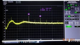
David's variable freq gen and a -100dbv ref cal tone:

 -141-149dBv
THx-RNMarsh
Last edited:
If we can get david's schematic and make pcb available for it (with profit to his family), we might be able to tweek it lower or use it as-is for many.
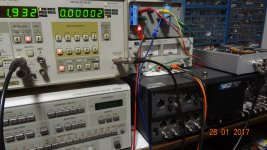
Here it is being tested by the Panasonic. It couldnt accurately measure it, so I went to the ShibaSoku and QA401 on the monitor port.
THx-RNMarsh
Here it is being tested by the Panasonic. It couldnt accurately measure it, so I went to the ShibaSoku and QA401 on the monitor port.
THx-RNMarsh
Attachments
Last edited:
I believe the AP's oscillator is open loop or only loosely disciplined.
That makes sense, it would mean they solved the problem. 🙂 My approach would be one of the new 20bit "R2R" DAC's with a de-glitcher and maybe an error correction cycle. I think one of these could approach -130dB so divided down as a lock in signal there should be no problem. SRC has a precision oscillator that does -120dB and exact frequency done this way. I remember being disappointed in the far out of band spurs. This is a lot of complexity to add to an instrument when you already have another solution.
Last edited:
If we can get david's schematic and make pcb available for it (with profit to his family), we might be able to tweek it lower or use it as-is for many.
Here it is being tested by the Panasonic. It couldnt accurately measure it, so I went to the ShibaSoku and QA401 on the monitor port.
THx-RNMarsh
I've been able to find 4 files: "dlb SVO V5 Sheet 1.pdf" and similar sheets 2-4.
I can post here if that's helpful and not in violation of copyright issues.
AP recognized the issue and solved it in software. My 2722 has that function but the newer models seem to have lost it. Instead of moving the hardware oscillator to 'bin center' it moves the samples to fall in bin centers, allowing high resolution windowless FFT. Anyone with some proficiency in say MathLab or Octave should find this a trivial exercise ;-)
This article might shed some light, in thinking about it if you have a single frequency oscillator you might want a simple pitch shifter.
Pitch Shifting Using The Fourier Transform | Stephan Bernsee's Blog
Interesting blog. Thanks!This article might shed some light, in thinking about it if you have a single frequency oscillator you might want a simple pitch shifter.
Pitch Shifting Using The Fourier Transform | Stephan Bernsee's Blog
Cheers, E.
Please post the files here.
Thx!
Thx!
I've been able to find 4 files: "dlb SVO V5 Sheet 1.pdf" and similar sheets 2-4.
I can post here if that's helpful and not in violation of copyright issues.
Did you use a modified or an unmodified Panasonic to get such low numbers?
If we can get david's schematic and make pcb available for it (with profit to his family), we might be able to tweek it lower or use it as-is for many.
Here it is being tested by the Panasonic. It couldnt accurately measure it, so I went to the ShibaSoku and QA401 on the monitor port.
THx-RNMarsh
Having assembled a reasonable test fixture I went on to sort through the 100 J108's i got from eBay. I switched to the Shibasoku for this since its fast and has a very low floor with 50 mV in in the test configuration. The fets raged from .004% HD2 to .008% HD2 with a Vdrop of 45 to 60 mV. The HD seemed to have a bigger variation. This batch of Jfets were National. The showstoper was the Siliconix Fets with .024% HD2 under the same circumstances. I was not expecting that. It suggests I'll need to test semis with the same specs for this. Maybe I'll need to get another 100 J108's.
In the test arrangement were you using the usual trick of feeding back 1/2 of the drain-source voltage to the gate? Under some conditions and with some JFETs, I have found that the exact value for optimum low distortion is not always exactly 0.5, so in my distortion analyzer I have a trimmer that can adjust that ratio slightly. Another question would be how the threshold voltage, IDSS and Rds-on of the Siliconix devices to the ones from eBay.
Cheers,
Bob
Please post the files here.
Thx!
Davida SVO schematics attached below.
Attachments
Last edited:
In the test arrangement were you using the usual trick of feeding back 1/2 of the drain-source voltage to the gate? Under some conditions and with some JFETs, I have found that the exact value for optimum low distortion is not always exactly 0.5, so in my distortion analyzer I have a trimmer that can adjust that ratio slightly. Another question would be how the threshold voltage, IDSS and Rds-on of the Siliconix devices to the ones from eBay.
Cheers,
Bob
I was actually testing them as a switch. The Boonton uses a lot for switching both in the oscillator and the attenuator (and the notch filter). The J108's showed much less distortion in the later Boontons so I thought I would sort for that. It seems Rds on is not a good enough parameter. In this case I tied the gate to the source through a 5K resistor to emulate the circuit. I tried swapping source and drain and the distortion was slightly higher. As a switch I could add the feedback resistor but there are 30 or more transistors so that's not too practical. I still might do some experiments.
I'll make some more formal measurements and post.
A very low distortion audio range oscillator can be easily constructed using a Raspberry Pi and a Pi DAC hat like the IQAudIO DAC. Install Raspbian and then use the command line to generate whatever frequency you may wish. You may also use a graphical interface like VLC and an audio file with the required frequency.
Not sure about that...here is data for the Pro DAC:
"Class leading audio; 114db SNR, and -94db THD"
Not really a very low distorsion generator....
"Class leading audio; 114db SNR, and -94db THD"
Not really a very low distorsion generator....
A very low distortion audio range oscillator can be easily constructed using a Raspberry Pi and a Pi DAC hat like the IQAudIO DAC. Install Raspbian and then use the command line to generate whatever frequency you may wish. You may also use a graphical interface like VLC and an audio file with the required frequency.
Sorry this is not possible. Every DAC on earth has more THD than a well designed analog oscillator.A very low distortion audio range oscillator can be easily constructed using a Raspberry Pi and a Pi DAC hat like the IQAudIO DAC. Install Raspbian and then use the command line to generate whatever frequency you may wish. You may also use a graphical interface like VLC and an audio file with the required frequency.
Sorry this is not possible. Every DAC on earth has more THD than a well designed analog oscillator.
Mola Mola
If they can't measure the distortion at -140dB they need better test equipment...
- Home
- Design & Build
- Equipment & Tools
- Low-distortion Audio-range Oscillator