Dirkw: I believe you are right. I also believe the pin-out of the LT1010 is wrong, pin 1 should be 2, 4 should be 2. Any comments? E
Dirkw: I believe you are right. I also believe the pin-out of the LT1010 is wrong, pin 1 should be 2, 4 should be 2. Any comments? E
I don't know yet, haven't had time to study it any more, just read through the application note this afternoon... so busy! Thanks for the tip. I am not talented at making circuit boards. I can do this on nice perf board, though 20volts output is way too much! I think I'd put a volume control before the input to the LT1010. Another problem is that the LT1006 is really only available in surface mount. I don't think ai can surface mount something on perf board.... can I?
I am thinking about designing the board for this oscillator once I am satisfied with..., also there are many suppliers of surfacemount to DIP adaptors
Scaling the output is not a problem. I am looking into replacing (or adding to) the LT1010 with a hi-slew balanced output device. E
Scaling the output is not a problem. I am looking into replacing (or adding to) the LT1010 with a hi-slew balanced output device. E
I am thinking about designing the board for this oscillator once I am satisfied with..., also there are many suppliers of surfacemount to DIP adaptors
Scaling the output is not a problem. I am looking into replacing (or adding to) the LT1010 with a hi-slew balanced output device. E
Oh cool. I'm in for a group buy. Balanced output would be fantastic!
Linear Technology sells the chips direct no problem, and apparently cheaper than Digikey.
CdS
Check with Jackinnj for the CdS.
In the Williams circuit, sometimes that CdS photocell can be hard to find in any venders stock.
Check with Jackinnj for the CdS.
It looks like this LT circuit has been discussed before:
http://www.diyaudio.com/forums/everything-else/41115-low-distortion-signal-generator-6.html
back in 2004.
http://www.diyaudio.com/forums/everything-else/41115-low-distortion-signal-generator-6.html
back in 2004.
This looks like the animal we need:
Excelitas Technologies Sensors - VTL5C10 - Optoelectronics & Lighting - Optocouplers/Optoisolators - Allied Electronics
I ordered 3 of them. I can share with mickeymoose or whoever is serious about designing a board.
Excelitas Technologies Sensors - VTL5C10 - Optoelectronics & Lighting - Optocouplers/Optoisolators - Allied Electronics
I ordered 3 of them. I can share with mickeymoose or whoever is serious about designing a board.
Last edited:
Random musings:
As low THD can be acieved only with low tol R+C in the Wien Bridge (stereo pot can have up to a +/-20% variation between segments), me thinks I will replace the dual-pot with a stereo digital pot and a small-value dual pot in series with the digital for in-between frequencies. Adjustment of the digital pot through a rotary encoder. This will require a digital frequency read-out, of course.....now this is getting involved! E
As low THD can be acieved only with low tol R+C in the Wien Bridge (stereo pot can have up to a +/-20% variation between segments), me thinks I will replace the dual-pot with a stereo digital pot and a small-value dual pot in series with the digital for in-between frequencies. Adjustment of the digital pot through a rotary encoder. This will require a digital frequency read-out, of course.....now this is getting involved! E
Random musings:
As low THD can be acieved only with low tol R+C in the Wien Bridge (stereo pot can have up to a +/-20% variation between segments), me thinks I will replace the dual-pot with a stereo digital pot and a small-value dual pot in series with the digital for in-between frequencies. Adjustment of the digital pot through a rotary encoder. This will require a digital frequency read-out, of course.....now this is getting involved! E
It would be a lot easier to make if I can just find a dual pot that has matched sections.
I could put 2 of these together:
http://www.bourns.com/data/global/pdfs/6574.pdf
Last edited:
if you can convince yourself that you don't really need continuous frequency adjustment (hint, hint), use resistors and switches. that will match better than ANY dual pot you can reasonably get a hold of and not break the bank in the process.
mlloyd1
mlloyd1
Second line: Total res range +/-10%
Who will match them, how many $s are they and what is the abolute linearity of each pot? I think I will stay with a digital solution
Of course, one can leave all the digital salad out and hook up a stereo pot to the pcb. E
Or use mollyd1 suggestions!
Who will match them, how many $s are they and what is the abolute linearity of each pot? I think I will stay with a digital solution
Of course, one can leave all the digital salad out and hook up a stereo pot to the pcb. E
Or use mollyd1 suggestions!
if you can convince yourself that you don't really need continuous frequency adjustment (hint, hint), use resistors and switches. that will match better than ANY dual pot you can reasonably get a hold of and not break the bank in the process.
mlloyd1
Yeah, that's a good idea. We can easily get resistors in 0.1% tolerance now.
Second line: Total res range +/-10%
Who will match them, how many $s are they and what is the abolute linearity of each pot? I think I will stay with a digital solution
Of course, one can leave all the digital salad out and hook up a stereo pot to the pcb. E
Or use mollyd1 suggestions!
Those Bourns precision pots have 0.1% (or was it 0.5%?) linearity, so if you get them to both "start" at the same resistive value, they should track within that window. They are about $70 each. I'm not sure how to gang them though.
I think he says in the application note that these pots should track within 0.1%. I haven't really found readily available ganged pots like that yet.
Last edited:
I sent an email to State Electronics asking for a suggestion on a dual gang pot where each section tracks the other better than 1%.
For another project, I've been working on a way to gang 2 single pots with tiny plastic sprockets and chain. I haven't built anything yet but I've got some of the parts.
It's easy to criticize but difficult to come up with a good working circuit.
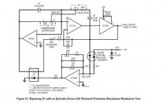
I believe that even with a 1% matched dual gang potentiometer the Light Dependent resistor amplitude control will still have significant voltage across it in the Wien bridge Linear Technology circuit. I have used Silonex opto couplers in the past and they aren't all that linear. I believe also that Hewlett Packard and Sound Technology used multiple switched close tolerance components to get around this problem.
The beauty of the phase shift based Oscillator used in the first schematic of this topic that theoretically the loop gain doesn't depend on the matching of the potentiometer gangs.
I think that a continuously variable frequency oscillator is useful for general purpose but that a switched frequency is OK for distortion measurements.
National Semiconductor (now Texas Instruments) have an LME49990 that claims low distortion when used with a gain of 1 so implies that the common mode signal doesn't cause bad distortion.
I think that the way to go is a Phase Shift based circuit. Use a sample and hold for the amplitude control so theoretically zero control voltage ripple and use an analog multiplier gain control for low distortion compared to Light Dependent Resistors or FETs.
Another fixed frequency option is to base the design on Cyril Bateman's design that is available on the web.
I guess that for computer control of the frequency a couple of Multiplying DACs could be used instead of motorized potentiometers that sounds complicated.
I wasn't criticizing the LT circuit. I'm not sure how you came to that conclusion. I'm not sure also what kind of point you're making.
I'm not suggesting motorized potentiometers at all. That's your idea.
If you've got a variable audio oscillator that has lower distortion than 0.0003%, then please show it. I'd like to see the LT circuit available as a PCB at least, but if not, then I'm going to build it on perf board.
I'm not suggesting motorized potentiometers at all. That's your idea.
If you've got a variable audio oscillator that has lower distortion than 0.0003%, then please show it. I'd like to see the LT circuit available as a PCB at least, but if not, then I'm going to build it on perf board.
- Home
- Design & Build
- Equipment & Tools
- Low-distortion Audio-range Oscillator