eventually, but I'm busy drinking right now - looks like I paid $80 and got a plastic screw top on my Japanese Scotch??
the inductor that the spice model comes from is a shielded ferrite type - I don't know just how high Q/low shunt C is needed in practice - CFA DS/app notes do warn of too much C on the inverting input - although I remember the equations saying that C to gnd causes peaking more than real instability - output to inverting input pure C however is a fail
the inductor that the spice model comes from is a shielded ferrite type - I don't know just how high Q/low shunt C is needed in practice - CFA DS/app notes do warn of too much C on the inverting input - although I remember the equations saying that C to gnd causes peaking more than real instability - output to inverting input pure C however is a fail
Last edited:
Sorry to hear about the plastic top. My rum when I was still able to drink had a cork.
Maybe we should take this over to your thread so we're not wondering too far off topic here.
Maybe we should take this over to your thread so we're not wondering too far off topic here.
I don't think this is off topic- its core to a usable state of the art oscillator.
JCX's work is really good. I fired it up and it ran with the defaults really quickly. However the distortion I get is about -80 dB, not -140 dB. I must be missing something. however I don't put a lot into those numbers from a sim. Building it is much better.
I have had really good results from the small surface mount shielded inductors from Coilcraft. My workaround for the shunt c of the inductor would be a ferrite bead in series selected to offset that shunt C. It should not take much. Looking at the charts a Fair-Rite #73 bead would have about the right impedance at 5 MHz up Fair-Rite Catalog |.
However, looking at the datasheet http://www.coilcraft.com/pdfs/0805ps.pdf the self resonant frequency of the inductor is near the passband at 7.5 MHz. That could be a problem. Coilcraft has models for their parts http://www.coilcraft.com/pdfs/spice_0805ps.pdf but it feels a little DIY as a model. I'll let JCX explore since he is way better at the spice stuff.
I don't think this is off topic- its core to a usable state of the art oscillator.
JCX's work is really good. I fired it up and it ran with the defaults really quickly. However the distortion I get is about -80 dB, not -140 dB. I must be missing something. however I don't put a lot into those numbers from a sim. Building it is much better.
I have had really good results from the small surface mount shielded inductors from Coilcraft. My workaround for the shunt c of the inductor would be a ferrite bead in series selected to offset that shunt C. It should not take much. Looking at the charts a Fair-Rite #73 bead would have about the right impedance at 5 MHz up Fair-Rite Catalog |.
However, looking at the datasheet http://www.coilcraft.com/pdfs/0805ps.pdf the self resonant frequency of the inductor is near the passband at 7.5 MHz. That could be a problem. Coilcraft has models for their parts http://www.coilcraft.com/pdfs/spice_0805ps.pdf but it feels a little DIY as a model. I'll let JCX explore since he is way better at the spice stuff.
Set the Max time step to 10ns or less in .tran.
I was concerned it might be off topic. However I agree if it related to low distortion oscillators it on topic. Even the low noise power supply stuff was relative but some thought differently.
I found with the integrator mode the input is less sensitive C but this might prove to be wrong in reality.
The only set back I can see is it can't be operated in non inverting mode. I tried and it just slammed against the rails.
I can't put a 300 ohm load on the oscillator. It's amplifier but it not a buffer.
By now JCX is down to half a bottle.
I think the sim runs fast with the .savebias .loadbias directives. Skips doing the dc operating point thing each run time I guess.
Last edited:
not a heavy drinker - I would kinda like to finish this one though since its so nice - they have a 18 year I really want to try now that I like the 12 year so much - but it takes me months to get through a bottle
the outer loop feedback and noise gain parts can be impedance scaled as long as you don't go too high - but I thought noise was important - no need for ~1 nV/rtHz input op amp with kOhm input/feedback
the inductor shunt in the CFA local loop gives >3rd order gain slope (judging by the 100 kHz phase dip) - quite sporty even though the sim seems to clip OK
my version of the diode clamp adds some odd harmonics when you go much higher in frequency as the inner node of the composite amp has to start swinging some V to drive the output op amp - if you make them all pn junction types instead of Schottky you get a few hundred more mV of internal Vswing before that happens
the clamping V can be made even higher if you want to ditch the inductor altogether for less alarming gain slope - make the center diode a LED or series a few Si pn types
Last edited:
not a heavy drinker - I would kinda like to finish this one though since its so nice - they have a 18 year I really want to try now that I like the 12 year so much - but it takes me months to get through a bottle
the outer loop feedback and noise gain parts can be impedance scaled as long as you don't go too high - but I thought noise was important - no need for ~1 nV/rtHz input op amp with kOhm input/feedback
the inductor shunt in the CFA local loop gives >3rd order gain slope (judging by the 100 kHz phase dip) - quite sporty even though the sim seems to clip OK
my version of the diode clamp adds some odd harmonics when you go much higher in frequency as the inner node of the composite amp has to start swinging some V to drive the output op amp - if you make them all pn junction types instead of Schottky you get a few hundred more mV of internal Vswing before that happens
the clamping V can be made even higher if you want to ditch the inductor altogether for less alarming gain slope - make the center diode a LED or series a few Si pn types
Noise is important. Buffer implies high Z input I thought. Will these composite not operate in non inverting?
It will if the clamp is removed. Is there another way of clamping? We only need 3V. Can we change clamping to 3V?
Last edited:
Will these composite not operate in non inverting?
You don't want to anyway as common-mode effects would cause high distortion.
Samuel
Samuel have you tried or have had any success in parallel op amps for higher current drive?
I tried doing this with 1468. The don't seem to like it. Although they were stable there was a distortion rise.
What was the configuration you tried? Just paralleling all pins doesn't work (consistently) for any opamp--the different offset voltages forces one of the opamp into current limiting.
Samuel
I fired it up and it ran with the defaults really quickly. However the distortion I get is about -80 dB, not -140 dB. I must be missing something. however I don't put a lot into those numbers from a sim. Building it is much better.
Opamp macro-models don't model distortion (except gross nonlinear behaviour such as slew-rate limiting), so simulating distortion is rather pointless...
Samuel
Can you explain the integrator thing bit more?
The transconductance of the input stage of a current feedback amplifier is (approximately) the reciprocal of the feedback network impedance at the inverting input port. So with a 1k-1k feedback network, the transconductance is 2 mS, or with a 100r-1k divider about 11 mS. The total (high-frequency) open-loop gain is given by the input stage transconductance times compensation capacitance, so can be modified by altering the feedback network--lower resistor values give higher open-loop gain. For a fixed feedback resistor and variable shunt resistor, we thus get an amplifier with constant bandwidth yet variable signal gain (in practice there are secondary effects which reduce BW at high gains).
This was for purely resistive feedback networks, i.e. flat wideband amplifiers. For composite opamps of the type JCX shows we want the second stage to have an integrating response below a given frequency f0 (usually some MHz) and unity gain above this (for a unity-gain stable composite opamp--at noise gains much above unity, higher gain above f0 might be appropriate). The integrating part gives the additional loop gain, and the unity gain section detoriates the phase margin of the first amplifier as little as possible.
To make the local feedback loop of the current feedback opamp stable its feedback network needs to have resistive characteristics above f0 (typically 1k). But to squeeze as much open-loop gain from the current feedback amplifier as possible the feedback network impedance (and thus input stage transconductance) should reduce below f0. So for a first-order integrator, the appropriate feedback network is a feedback resistor and a shunt inductor. Unfortunately the required inductance values become inconveniently large. Possibly it would be necessary to put several smaller inductors in series to get a sufficiently high resonance frequency.
Using a feedback capacitor doesn't work as well as an inductor, because it does not increase the input stage transconductance below f0 (and thus the distortion contribution of the current feedback amplifier is much higher), and gives a minimum gain of typically 6 dB above f0 (which needs to be compensated elsewhere).
These considerations are the reason I'm not using current-feedback amplifiers. But there are of course many ways to skin the cat, and I see that the DSL drivers are attractive to use because of their output current (isn't there one with voltage feedback..?).
Samuel
Last edited:
What was the configuration you tried? Just paralleling all pins doesn't work (consistently) for any opamp--the different offset voltages forces one of the opamp into current limiting.
Samuel
I've read the notes from Walt J. Bob P. and whoever wrote the LT notes, probably Jim.
The AD notes are quite aggressive suggesting directly parallel the op amps. Bob P disagrees and shows a way of dealing with the op amp offsets forcing the offset to equalizes. LT was somewhere in between.
Directly paralleling the LT1468 did note work. Not only do the op amp cook but tend to oscillate as well. 100 ohm resistors at the outputs helped but I suspect the op amps were on the edge of instability. The distortion elevated rather than reduced.
This is loosely quoted.
I do recall Nelson stating in one of Bob C's threads that whenever he encounter distortions beyond what's expected in his amplifiers he usually finds something oscillating within the amplifier. My experience with the 1468 and other op amps tends to agree with that statement.
I've read the notes from Walt J. Bob P. and whoever wrote the LT notes, probably Jim. The AD notes are quite aggressive suggesting directly parallel the op amps. Bob P disagrees and shows a way of dealing with the op amp offsets forcing the offset to equalizes. LT was somewhere in between.
Can you point me to the resources you mention?
Samuel
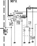
RE Paralleling opamps- I saw in the Yamaha TX950 tuner they did parallel the two 1/2's of an NJM2068 in production. They did this to get the noise floor lower. Since the parts were on a common substrate the offset differences may have been very small. The schematic clip below is not easy to follow but I traced the PCB and confirmed they just paralleled the pins. That was a high volume product so they could not sort opamps for offset differences.
I swapped the OPA1612 for an LME49990 in JCX's simulation and it all worked fine. As Samuel points out the distortion it would show is pretty meaningless but the transient response to a fast edge seems well controlled and free of signs of instability even when driving the output to clipping.
Its worth trying as a PCB. I don't think a breadboard would be too successful since the CFA has so much bandwidth and power.
Attachments
but we do have a lot more info on real world distortion of the TPA6120/THS6012
between the 2 DS we have measured heavy load distortion plots to MHz
we should expect if feedback is doing its thing - any extra feedback added by the input op amp to the composite global loop will be directly reducing the TPA6120/THS6012 DS plotted distortion - whatever the local feedback around the output CFA needed for stability - by the factor of the added feedback
all of course subject to the limitations of implementation in such high gain circuits - ps coupling, gnd common impedance - worse with Class AB
and of course the feedback passives' performance limits can't be evaded
I am playing with the composite amp integrator compensation - clipping seems to need more clamping circuits
I have biased the 2 outputs of the 2 CFA in a package against each other in push-pull Class A with ~200 mA bias current and 1 Ohm current sharing R with the TPA6120
in theory this should give reduced ps impedance coupled distortion in a circuit since all the ps draw is a linear function of the linear output demand with Class A
I have always used per amp local feedback and current sharing R for paralleling op amp outputs
Last edited:
Can you point me to the resources you mention?
Samuel
Yes but I'll have to dig them up. Some are data sheets and some app notes.
Bob's I'll have to search the net for. I'll look in my folder first. Give me a bit time.
RE Paralleling opamps- I saw in the Yamaha TX950 tuner they did parallel the two 1/2's of an NJM2068 in production. They did this to get the noise floor lower. Since the parts were on a common substrate the offset differences may have been very small. The schematic clip below is not easy to follow but I traced the PCB and confirmed they just paralleled the pins. That was a high volume product so they could not sort opamps for offset differences.
I swapped the OPA1612 for an LME49990 in JCX's simulation and it all worked fine. As Samuel points out the distortion it would show is pretty meaningless but the transient response to a fast edge seems well controlled and free of signs of instability even when driving the output to clipping.
Its worth trying as a PCB. I don't think a breadboard would be too successful since the CFA has so much bandwidth and power.
The OPA1612 is a better op amp. I use it in the multiplier of my SVO. Very nice indeed but to each there own.
I was checking for stability, not performance. I have the TPA6120 demo board here and I'll set it up and measure it shortly. What conditions should I be testing for? output V and load?
I was checking for stability, not performance. I have the TPA6120 demo board here and I'll set it up and measure it shortly. What conditions should I be testing for? output V and load?
Sure.
Keeping in mind this is a radio frequency amplifier you might check for it's susceptibility to unwanted signals as well as power supply issues. I have some concerns for using this as an amplifier for a test oscillator. Hate to see a power amp go up in smoke because of a poor choice. I guess I don't need to mention noise and distortion. Power into load vs max output voltage sounds good.
The AD notes are quite aggressive suggesting directly parallel the op amps. Bob P disagrees and shows a way of dealing with the op amp offsets forcing the offset to equalizes. LT was somewhere in between.
Directly paralleling the LT1468 did note work. Not only do the op amp cook but tend to oscillate as well. 100 ohm resistors at the outputs helped but I suspect the op amps were on the edge of instability. The distortion elevated rather than reduced.
I also tried to parallel the 1468... and got same results you did. I thought at the time... IIRC.... that it was dc offsets that caused the heating up ... maybe they were trying to sink/source the dc offset preventing direct parallel use in the oscillator role for the HP339A. I'll have to find the Bob P offset equalizing method.
When I get back to my lab in California I am going to try a lot of IC's to see which can be directly paralleled and which need some small additional fix to make them useable in parallel.
But dont wait for me....
THx-RNMarsh
- Home
- Design & Build
- Equipment & Tools
- Low-distortion Audio-range Oscillator