JCX's link explains the diodes. They help recovery from overload.
Maybe Samuel can offer insight on using a composite amp inside the oscillator. With so much gain available the amplifier distortion can be reduced even more. However it may not be the limiting factor in distortion in the first place.
I saw that after posting the question.
JCX's link explains the diodes. They help recovery from overload.
Maybe Samuel can offer insight on using a composite amp inside the oscillator. With so much gain available the amplifier distortion can be reduced even more. However it may not be the limiting factor in distortion in the first place.
The limiting factor in my SVO appears to be from loading on the op amps. Particularly the second integrator because it sees loading from both the tuning network, multiplier input and controller input. I was able to improve this some by placing a Jfet op amp as buffer between the leveling controller and oscillator stages. A composite including an high current output buffer I think would solve the problem and the oscillator could be operated at a much higher output. This could eliminate the need for an output buffer/amplifier. A buffered op amp would handle smaller resistors and larger caps in the integrators which would bring the noise some. An extended amplifier bandwidth would improve the loop stability because the Q enhancement effect would be less.
Can we make a composite amplifier with a high current buffer stage happy with functioning as an integrator?
CFAs can't be used as integrators but could they work in composite design? If so then the THS6012 might be good candidate.
Last edited:
yes you can make a composite op amp integrator - the outer integrator cap feedback looks like unity gain feedback for stability - either you need a buffer 5-10x faster than your input op amp or you need some compensation inside the loop
Here are a few numbers to put the impedance/noise issues in context:
A 600 Ohm resistor will have a noise floor of -125 dBV in a 30 KHz band (typical distortion measurement band) and is about 3 nV/rtHz. What this means is that an amplifier needs to be less than about 2 nV/rtHz for the amplifier to be lower noise than the 600 Ohm resistor. This is significant for the inverting amp (like Samuel's above).
Today's best distortion analyzers seem to be about -115 dB THD+N in that 30KHz band. I would want to be sure that an oscillator + buffer was well below that for noise so for a 3V source we would have approx -135 dB SNR with 600 Ohms (not including source noise). 600 Ohms is a reasonable load for the oscillator it seems.
Maybe the best option for gain control is varying the feedback resistor to range from unity to +10 dB in the buffer amp and then instead of a constant impedance attenuator a resistive divider that would have constant noise. One that's effective source resistance decreases as you reduce the signal (kind of like the GR Microvolter). At high attenuations the resistors will be very small making for a low source impedance.
Last edited:
When we were using a HP339A for its flexibility - osc with selectable freqs - I suggested a composite amp for oscillator and we got several links and replies about it at that time. [dont ask me where they are]..... But I dont like to go in circles on a subject. When we start repeating issues we already looked at, I think we are done.
If this design is completed, as is, lets test and see where we are and then we can decide what else can be done and best way. Meanwhile, we can also built and test the composite buffer.
Other means and methods can be pursued if there is the potential to be even better.... another new design. But, we need to stop and test what has been done. Any other designs can be compared to this first major effort to reset the bar.
THx-RNMarsh
Last edited:
Here are a few numbers to put the impedance/noise issues in context:
A 600 Ohm resistor will have a noise floor of -125 dBV in a 30 KHz band (typical distortion measurement band) and is about 3 nV/rtHz. What this means is that an amplifier needs to be less than about 2 nV/rtHz for the amplifier to be lower noise than the 600 Ohm resistor. This is significant for the inverting amp (like Samuel's above).
Today's best distortion analyzers seem to be about -115 dB THD+N in that 30KHz band. I would want to be sure that an oscillator + buffer was well below that for noise so for a 3V source we would have approx -135 dB SNR with 600 Ohms (not including source noise). 600 Ohms is a reasonable load for the oscillator it seems.
Maybe the best option for gain control is varying the feedback resistor to range from unity to +10 dB in the buffer amp and then instead of a constant impedance attenuator a resistive divider that would have constant noise. One that's effective source resistance decreases as you reduce the signal (kind of like the GR Microvolter). At high attenuations the resistors will be very small making for a low source impedance.
For the attenuator I posted a link to the constant input resistance version for example will;
Input resistance ranges from 99.33R to 100.4R.
Output resistance ranges from 0 to 47.07R.
What I like about this particular attenuator is that it's binary weighted. Saves on parts and easily controlled by a micro controller. 7 relays gets us 0db to -128dB
With constant input R an passive output can be placed on the output of the amplifier to limit the band width. This will clear up a lot of the wide band noise. I think something higher than 50R and much lower than 600R would be a good compromise.
The R can be made higher but then the noise goes up. Any of the composite amps can have a buffer added to them or stick a discrete diamond bridge in front of one.
Output Z from atten of 0-47 Ohms and max output of 2.5v rms. That is something I would be happy to use.
The distortion seems it is going to be very, very good. I plan to use FFT analysis, mostly. But, the low noise (THD+N) is a bonus.
THx-RNMarsh
The distortion seems it is going to be very, very good. I plan to use FFT analysis, mostly. But, the low noise (THD+N) is a bonus.
THx-RNMarsh
Last edited:
Output Z from atten of 0-47 Ohms and max output of 2.5v rms. That is something I would be happy to use.
The distortion seems it is going to be very, very good. I plan to use FFT analysis, mostly. But, the low noise (THD+N) is a bonus.
THx-RNMarsh
Like I said Rick it will be modular. you can set it however you like.
Would you also provide it as I would use it - and any other modules - when you send it in for testing???? I'll test it both with and without modules.
-Richard
-Richard
My humble opinion/experience to some of the composite opamp topics that have been touched in the last few posts:
* Yes, the diodes at the output of U1 improve the recovery from overload. Even under fully-scale 100 kHz output the voltage swing at U1 output is just a few dozen mV, so the diodes don't conduct significant current.
* While it is possible to use current feedback opamps in certain configurations I have not yet found convincing arguments for their application. If the output drive of the LT1468 is insufficient, it could be replaced with e.g. a THS4031. Yet this opamp has much poorer (audio frequency) THD and current noise than the LT1468--at least the former is mitigated by the fact that the R1-R2 attenuator could be relaxed or perhaps even omitted because of the much higher unity-gain BW of the THS4031.
* Adding an output buffer to the composite opamp will compromise the phase margin. With the ~30 MHz unity gain frequency of the LT1468 this might be difficult to address.
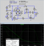
* I'm successfully using composite opamps for the oscillator loop. Difficulties such as latch-up or HF oscillation may arise during power-up and overload.
And a brief digression on estimating the distortion performance of the LT1115-LT1468 composite opamp. The LT1468 shows about -150 dB input-referred 3rd harmonic distortion voltage (other harmonics are lower) when driving 600 Ohm at 1 kHz in a noninverting configuration (data taken from my opamp distortion measurement series). The LT1115 has almost 90 dB open-loop gain at 3 kHz (3rd harmonic of 1 kHz), which is reduced to about 80 dB by the R1-R2 attenuator. The LT1115 can be considered essentially distortion free as it operates with very low output voltage and current swing. Thus the input-referred 3rd harmonic distortion voltage of the composite opamp is at -230 dB (with my measurement setup I can verify this performance at the -180 dB level by running them at 60 dB noise gain.)! With the noise gain of 6 dB of the shown unity gain configuration, the effective distortion referred to the output is still beyond any practical needs.
The above analysis neglects that U2 may inject distorted currents in the feedback loop through its inverting input port. However this should not usually cause significant distortion in a practical context if the feedback network has reasonably low impedance.
Again, the real challenges are in the design of the feedback network and the handling of layout/power supply effects.
Samuel
* Yes, the diodes at the output of U1 improve the recovery from overload. Even under fully-scale 100 kHz output the voltage swing at U1 output is just a few dozen mV, so the diodes don't conduct significant current.
* While it is possible to use current feedback opamps in certain configurations I have not yet found convincing arguments for their application. If the output drive of the LT1468 is insufficient, it could be replaced with e.g. a THS4031. Yet this opamp has much poorer (audio frequency) THD and current noise than the LT1468--at least the former is mitigated by the fact that the R1-R2 attenuator could be relaxed or perhaps even omitted because of the much higher unity-gain BW of the THS4031.
* Adding an output buffer to the composite opamp will compromise the phase margin. With the ~30 MHz unity gain frequency of the LT1468 this might be difficult to address.
* I'm successfully using composite opamps for the oscillator loop. Difficulties such as latch-up or HF oscillation may arise during power-up and overload.
And a brief digression on estimating the distortion performance of the LT1115-LT1468 composite opamp. The LT1468 shows about -150 dB input-referred 3rd harmonic distortion voltage (other harmonics are lower) when driving 600 Ohm at 1 kHz in a noninverting configuration (data taken from my opamp distortion measurement series). The LT1115 has almost 90 dB open-loop gain at 3 kHz (3rd harmonic of 1 kHz), which is reduced to about 80 dB by the R1-R2 attenuator. The LT1115 can be considered essentially distortion free as it operates with very low output voltage and current swing. Thus the input-referred 3rd harmonic distortion voltage of the composite opamp is at -230 dB (with my measurement setup I can verify this performance at the -180 dB level by running them at 60 dB noise gain.)! With the noise gain of 6 dB of the shown unity gain configuration, the effective distortion referred to the output is still beyond any practical needs.
The above analysis neglects that U2 may inject distorted currents in the feedback loop through its inverting input port. However this should not usually cause significant distortion in a practical context if the feedback network has reasonably low impedance.
Again, the real challenges are in the design of the feedback network and the handling of layout/power supply effects.
Samuel
Last edited:
Samuel have you tried or have had any success in parallel op amps for higher current drive?
I tried doing this with 1468. The don't seem to like it. Although they were stable there was a distortion rise.
Any attempt to add a buffer caused the LT1115/1468 sim composite to oscillate.
I tried doing this with 1468. The don't seem to like it. Although they were stable there was a distortion rise.
Any attempt to add a buffer caused the LT1115/1468 sim composite to oscillate.
Last edited:
I can't tell if you guys are thinking literally "add a buffer" with 2 op amps already in the composite - no need with a DSL driver CFA as the 2nd op amp at the output of the composite
they supply gobs of current at extremely low distortion and their speed can make the composite loop compensation easier
I like the TPA6120/THS6012 because it is designed for high current output at low distortion to MHz for DSL line driving - others may do as well but its handy having the audio frequency specs - 1.5W into 32 Ohms at single digit ppm distortion to 20 kHz
I recommend reading both datasheets - they are the same chip - the THS6012 DSL driver DS gives the min working Iout as 400 mA into 25 Ohms with 800 mA typ Isc
from the TPA6120 datasheet plots we can see a lower audio frequency distortion rise at high power - to 10s of ppm - presumably thermal modulation that the multiloop composite has no problem cleaning up with the input op amp having essentially no signal related power dissipation and consequently no signal related thermal effect and the input op amp typically supplies >60 dB added loop gain at low audio frequencies for feedback correction of the output op amp
I initially tried the LM6171/2 as the output device in my 1st experiments at advanced multiloop composite amplifiers over decade ago- even paralleling them - they are a bit twitchy but they worked well enough to make some progress in my understanding the nonlinear stability issues - but I really wouldn't want to try to repeat the experience at low/unity gain with the 6171 - even gains of 4-5 help the stability a lot
CFA op amps have the additional feature of being able to over compensate by increasing their local feedback R when you don't need their ultimate speed
CFA don't have huge DC/low audio open loop gain so they do contribute less added loop gain to the composite - but even with modest overcompensation they can give 50-60 dB over the extended audio frequency range - calculated using the transresistance that is found in the THS6012 DS
of course with that single digit ppm 20 KHz distortion of the TPA6120 alone you don't nee much added loop gain for linearizing the output - and the input op amp is likely already fine when it sees next to no output loading and mV output swing - I got quite remarkable numbers with even TL070 input op amp
I modify the local feedback around the CFA output op amp to get more audio frequency loop gain in the composite amp outer loop - the modified integrator series R,C feedback works fine with CFA - just needs to look resistive in the correct amount as you near the CFA's local loop gain intercept frequency - over 10 MHz - although the composite loop stability will usually require using lower zero corner frequency in the CFA local feedback
Last edited:
In short I'm talking about a high output current buffer with a gain of 4 to 5.
Here's the long winded.
When I say the SVO needs to be buffered I mean it's already loaded to it's maximum for the distortion levels I'm getting at 2.5Vrms output. With any additional loading I can see the distortion rise. The resistors used around the ring loop and the tuning currents are not low and large by any means but it all adds up in the end. It's a balance between low R, to keep the noise down, and distortion from loading effects. This is one requirement.
To make the oscillator more useful the output level needs be stepped up. A gain of 4 to 5 is needed and if this amplifier is to drive a low Z attenuator then we need some current greater than what a general purpose op amp can provide. A buffer with a gain of 4 or 5 that's capable of delivering a few hundred mA will do. The distortion needs to be better than -150dB from 1kHz to 20kHz. The noise at unity should be as low as possible well below 5nV/rtHz preferably zero. The nominal R of the attenuator is not important. Well below 600 ohms. I see no reason to adhere to an old obsolete standard of 600 ohms or to go as low as a 50 ohm RF standard. The R of the attenuator will be as low as reasonably possible. There are many factors involved in making that decision and I'm still looking at that. Less noise and distortion from any one thing is best, it all adds up.
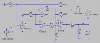
If its an inverting amplifier the TPA6120 as an output amp and even an LME49720 dual would get both phases on the output pretty easily. Witht he inverting amp and 600 Ohms in the noise of the LME49720 will not be an issue. Running the two 1/2s of the TPA6120 in opposite phase may reduce some of the secondary distortions that come from power supply modulations etc. You could use the LME49990 or AD797 or LT1115 as lower noise alternatives if noise is an issue. Checking my records the limit of the TPA6120 is about -109 at the second harmonic in noninverting mode. With its power bandwidth of 160 MHz it won't be the limiting factor in closing the loop.
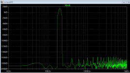
I reworked my old compos.asc sim with new low noise input OPA1611 and the THS6120/TPA6120 for the output
trying for all the loop gain that can be squeezed to the outer loop I get 20 kHz THD <-160 dB 7 Vrms/50 Ohm load - for whatever the sim # is worth
the simmed loop gain shaping gives near 60 degree phase margin while having over 120 dB loop gain to 30 kHz
the modified integrator feedback and the 100uH inductor shunt push all the gain that can be had from the CFA output op amp into the outer loop for the extended audio frequency range - haven't tried the inductor trick in the real world - but I did choose a model that has a parasitic parallel C so maybe its not too unrealistic
also used noise gain shunt at the input to improve the loop gain intercept region
I find LTspice convergence problems with these ridiculous high loop gains - if you mod the circuit much you may have to retry the .savebias/.loadbias (un/re comment the lines on the schematic, possibly esc out of long startup stepping)
should run in the composII folder - I think I got the models and bias files too
Attachments
Last edited:
If its an inverting amplifier the TPA6120 as an output amp and even an LME49720 dual would get both phases on the output pretty easily. Witht he inverting amp and 600 Ohms in the noise of the LME49720 will not be an issue. Running the two 1/2s of the TPA6120 in opposite phase may reduce some of the secondary distortions that come from power supply modulations etc. You could use the LME49990 or AD797 or LT1115 as lower noise alternatives if noise is an issue. Checking my records the limit of the TPA6120 is about -109 at the second harmonic in noninverting mode. With its power bandwidth of 160 MHz it won't be the limiting factor in closing the loop.
I ran a spice analysis of a composite with the TPA6120 - LME49990, AD797, LT1115 and OPA1611. The LME49990 didn't as well as the others. LT1115 has a problem when over driven. The TPA6120 doesn't have quite enough gain to push the distortion to were I want it, at least in spice land, and remain stable so I used two. According to spice it works very well but it's a bit marginal on the stability. I'll try it and see what happens.
I can bundle this into a zip if you want to play around with it.
1.3uVrms @ 30kHz BW
Attachments
I reworked my old compos.asc sim with new low noise input OPA1611 and the THS6120/TPA6120 for the output
trying for all the loop gain that can be squeezed to the outer loop I get 20 kHz THD <-160 dB 7 Vrms/50 Ohm load - for whatever the sim # is worth
the simmed loop gain shaping gives near 60 degree phase margin while having over 120 dB loop gain to 30 kHz
the modified integrator feedback and the 100uH inductor shunt push all the gain that can be had from the CFA output op amp into the outer loop for the extended audio frequency range - haven't tried the inductor trick in the real world - but I did choose a model that has a parasitic parallel C so maybe its not too unrealistic
also used noise gain shunt at the input to improve the loop gain intercept region
I find LTspice convergence problems with these ridiculous high loop gains - if you mod the circuit much you may have to retry the .savebias/.loadbias (un/re comment the lines on the schematic, possibly esc out of long startup stepping)
should run in the composII folder - I think I got the models and bias files too
I like this one better.
What do you propose for an inductor. 100u is a fairly large air core.
Last edited:
I reworked my old compos.asc sim with new low noise input OPA1611 and the THS6120/TPA6120 for the output
trying for all the loop gain that can be squeezed to the outer loop I get 20 kHz THD <-160 dB 7 Vrms/50 Ohm load - for whatever the sim # is worth
the simmed loop gain shaping gives near 60 degree phase margin while having over 120 dB loop gain to 30 kHz
the modified integrator feedback and the 100uH inductor shunt push all the gain that can be had from the CFA output op amp into the outer loop for the extended audio frequency range - haven't tried the inductor trick in the real world - but I did choose a model that has a parasitic parallel C so maybe its not too unrealistic
also used noise gain shunt at the input to improve the loop gain intercept region
I find LTspice convergence problems with these ridiculous high loop gains - if you mod the circuit much you may have to retry the .savebias/.loadbias (un/re comment the lines on the schematic, possibly esc out of long startup stepping)
should run in the composII folder - I think I got the models and bias files too
Your using some tricks in here I've never seen before. Can explain the integrator thing bit more?
- Home
- Design & Build
- Equipment & Tools
- Low-distortion Audio-range Oscillator