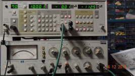
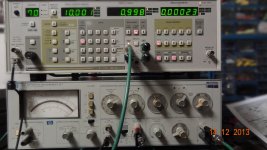
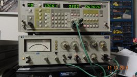
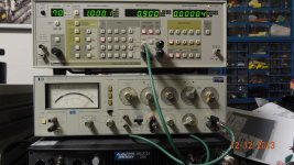
You could make a passive low pass filter and verify that it reduces the second or third harmonic by a known amount (and doesn't create new harmonics of its own) and then see if the reported harmonics of the ultra low distortion source drop by the predicted amount. If they do then the analyzer isn't generating them. If not there is clearly interaction. A single pole filter should get 3-6 dB on the second and approx 12 dB on the third. A two pole filter (2R's and 2C's) should do more and be more obvious. You may be able to do this with the B&K passive notch in the passive mode.
The Shibasoku is unique among these analyzers with no servo tuning. On paper that should make for lower residual distortion.
The affect is well documented -- at least by A-P.
View attachment ADC.pdf
The unique design by ShibaSoku and the brands selling those similarly made by Matsushita allows them to spec their measured 2H at +/- 1 dB in their data sheets.
Thx-RNMarsh
If you're looking at a signal of constant frequency (and its harmonics, spurs, whatever) wouldn't a 24 bit ADC oversampled and averaged 4*4*4 times give you over 160dB? In which case, what do I do with my SR785?
Would this work? How can we do it!? What IC parts can be used?
Thx-RNMarsh
I'm not aware of fundamental notch depth limitations. Note that the -155 dB figure is not a noise measurement in a known equivalent noise bandwidth (e.g. changes with FFT parameters) and thus not suitable to define any hard limits.
Samuel
In the AP2722 (post #3253), the measured noise of the analog combination "generator - analyzer" is practically -116dB in a 10Hz-22kHz bandwidth and just in these conditions the system of automatic tuning brings the fundamental harmonic at the notch filter output down to -142dB (this figure we get from FFT).
Surely, the automatic system would operate easier if the background noise was lower, say -130dB, but this is impossible because of inevitable thermal noise in components.
The fundamental notch depth largely depends on the system's performance, the limitations here come from a finite gain within the tuning channels, voltage offsets, interferences etc.
The fundamental notch depth largely depends on the system's performance, the limitations here come from a finite gain within the tuning channels, voltage offsets, interferences etc.
Another, more subtle, effect is this one: the simple phase-sensitive detectors usually employed (effectively multiplying with a square wave) are sensitive to odd-order harmonics. So for distortion measurements with high odd-order harmonic content, the notch depth decreases.
Fortunately this is no practical problem, as with signals that have high distortion, the fundamental rejection becomes less critical anyway...
Samuel
I saw this yesterday... didn't know why it changed... thx for the explaination.
BTW - does this have any affect on odd-even harmonic measurement accuracy (especially at very low harmonic levels)?
-RNM
Last edited:
BTW--does this have any affect on odd-even harmonic measurement accuracy (especially at very low harmonic levels)?
No, should not have any significant effect.
Samuel
Last edited:
Here's my tuned up HP-339A oscillator; THD+N and THD [1v rms/1KHz]
[click on picture and then zoom in]
View attachment 387172
View attachment 387173
Thx-RNMarsh
Richard which osc IC does that HP have in it? Also what is H3 at 1K?
Richard which osc IC does that HP have in it? Also what is H3 at 1K?
LT1468. 3H is lower than 2H in distortion. [To some degree this is variable by tuning values in the circuit.]
Note: All the IC opamps I tried are sensitive to the Z of the circuit values.... the THD distortion changes - with same freq. and increased or decreased Z. This test was at lower Z values of the X100 range and X10 freq = 1KHz. If you change the range to X1K and X1 = 1KHz the distortion is slightly higher.
-THx RNMarsh
Last edited:
Here's my tuned up HP-339A oscillator; THD+N and THD [1v rms/1KHz]
[click on picture and then zoom in]
View attachment 387172
View attachment 387173
Thx-RNMarsh
And, here is the THD at 10KHz


Hi Guys,
Any thoughts on using IR remote for tuning and level setting an oscillator?
It's not too difficult to do and offers complete isolation. No PC control required.
It's certainly a lot less expensive than control knobs and switches for manual control.
There's not a lot of USB bandwidth required for control so a USB IR stick could be make to work for PC control.


Hi Guys,
Any thoughts on using IR remote for tuning and level setting an oscillator?
It's not too difficult to do and offers complete isolation. No PC control required.
It's certainly a lot less expensive than control knobs and switches for manual control.
There's not a lot of USB bandwidth required for control so a USB IR stick could be make to work for PC control.
😎🙂
Wouldn't the IR receiver require placing a microcontroller - and associated (always running) clock signals for both the uC and the IR receiver subsystem - into the oscillator box? If we're looking for total corruption in the sub-ppm range, any solution that includes an always-running clock strikes me as another problem to solve.Hi Guys,
Any thoughts on using IR remote for tuning and level setting an oscillator? . . . .
But if it could be done with a communication protocol that uses a "wake up " signal and kills the clocks when data isn't being actively transferred, you may have a good idea.
Dale
Actually a high frequency clock running has posed no problems at all. Simply hasn't show up in the audio spectrum. Doesn't seem to bother the EMU 0204. I haven't tried it with the QA400. But these issues can be cleared up by using isolated powers with separate grounds.
20 MHz is way outside the band of interest. If were really a problem digital audio simply wouldn't work. I had no problem running a PIC micro beside the oscillator. However I think either galvanic or optical isolation is a must. RF shielding around the micro could be added.
I'm not worried about it.
It does solve an issue found with USB grounding with oscillators and sound cards. USB grounds really don't mix very well at sub ppm levels.
But if it could be done with a communication protocol that uses a "wake up " signal and kills the clocks when data isn't being actively transferred, you may have a good idea.
Dale
This is in fact what some test equipment makers do when making very, very low thd level measurements.... they shut down all unnecessary circuit business when making a measurement/acquiring data. No other digital circuits running when they are not needed for the measurement. Such as, clocks and digital circuitry used for a digital display/readout and other clocks and free running portions not used for measurement.
Thx-RNMarsh
Last edited:
Micro controls have a sleep mode. I can put the controller to sleep when not in use. This shuts down all clock signal except what,s needed to wake the processor up. It can wake up on an interrupt.
Micro controls have a sleep mode. I can put the controller to sleep when not in use. This shuts down all clock signal except what,s needed to wake the processor up. It can wake up on an interrupt.
A software or hardware interrupt works fine.
-RNM
- Home
- Design & Build
- Equipment & Tools
- Low-distortion Audio-range Oscillator

