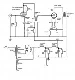
Anode dissipation is the voltage between cathode and anode times the anode current. So with the values indicated in the schematic the anode dissipation is: (415 - 70.5) x 0.046 = 15.85 Watt.
The current of 46 mA doesn't fit with the DC resistance of 308 Ohm of the primary of the OPT as stated in the datasheet (see: http://www.monolithmagnetics.com/sites/default/files/datasheet%20SX-11%20old%20format.pdf ). The voltage drop over the primary with 46 mA would have to be: V = I x R = 0.046 x 308 = 14.2 V. But the voltages in the schematic give: 423 - 415 = 8 V.
The current of 46 mA doesn't fit with the DC resistance of 308 Ohm of the primary of the OPT as stated in the datasheet (see: http://www.monolithmagnetics.com/sites/default/files/datasheet%20SX-11%20old%20format.pdf ). The voltage drop over the primary with 46 mA would have to be: V = I x R = 0.046 x 308 = 14.2 V. But the voltages in the schematic give: 423 - 415 = 8 V.
banpuku - with cathode resistor (self bias) the voltage inside the tube is cathode to anode: 415V - 70.5V = 344.5V
70.5V at cathode: 1500 + 25 = 1525r catode, 70.5V/1525r = (bias current) 0.04623mA x 344.5V = 15.9 Watt dissipation of 45B. You have bias 46.2mA, at -70.5V grid, at 344.5V plate. This values are circa in line with the AC heated 45B plate curves of Emission Labs. You have luck, your tubes are good. In the past you have measured and calculated wrong. (And most of your SE 45B schematics have wrong values. This is tube basics) If you would have the real new values of your 45B, you could compare them to see how much wear out you have now.
What is with the battery +- orientation on C3g cathode ?
I thought you would replace all 3 psu caps with CDE. Blitz is using the CDE 947D for all psu caps.
Lauscher: To date, I have replaced only C2 with a CDE. Eventually I will replace C1 and C3. Regarding the battery, (+) is connected to cathode and (-) is connected to ground.
euro21: 5.6uF is correct. I originally had a 30uF Russian PIO and replaced it with a Jantzen Supreme cap (I only have a 5.6uF available). Eventually, if I stay with RC cathode bias, I will upgrade the cap to the proper value (likely 30uF). I am contemplating fixed bias to eliminate the cap all together.
euro21: 5.6uF is correct. I originally had a 30uF Russian PIO and replaced it with a Jantzen Supreme cap (I only have a 5.6uF available). Eventually, if I stay with RC cathode bias, I will upgrade the cap to the proper value (likely 30uF). I am contemplating fixed bias to eliminate the cap all together.
I think that 45B cathode decoupling capacitor value (5.6uF) is a typo, because with this value the LF bandwidth -3dB at about 21Hz.
Normally the ultrapath capacitor value is ck/mu

I changed the 45B Rk to 1250ohms. This gives:
Ua = 416.5V
bias = 67V
52.5 mA
Ua - bias = 349V
67/(1250+25) = 52.5 *349 = 18.3 watts (83% of 22 watt max)
Ua = 416.5V
bias = 67V
52.5 mA
Ua - bias = 349V
67/(1250+25) = 52.5 *349 = 18.3 watts (83% of 22 watt max)
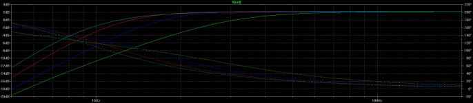
This is the effect of ultrapath capacitor value:
5.6uf (green), 15uF (blue), 30uF(red), 47uF.
I have a 30uF wima DCLink. I will give it a try.
I changed the 45B Rk to 1250ohms. This gives:
Ua = 416.5V ....
52.5 mA
With 423V supply?
Are you sure that OPT is SX-11?
It has 308R primary DCR, so the calculation don't match.
BTW ultrapath ....
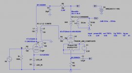
Simulation:
Hum on output (B+ hum 100mV 100Hz)
Ultrapath (30uF): 6.84mV RMS
Cath. decoupling (30uF): 1.97mV RMS
Simulation:
Hum on output (B+ hum 100mV 100Hz)
Ultrapath (30uF): 6.84mV RMS
Cath. decoupling (30uF): 1.97mV RMS
euro21: I find something very interesting / strange. The Ua & C2 B+ changes when the Rk changes.
Here are some measurements / tests taken 3 hours ago:
C2 B+ 432, Ua 425, Rk 2000
C2 B+ 430, Ua 421, Rk 1750
C2 B+ 427, Ua 420, Rk 1250
C2 B+ 425, Ua 414, Rk 1000
C2 B+ 410, Ua 380, Rk 250
Now, I just measured both mono-blocks. Remember, this is 3 hours after I took the measurements above.
Left mono-block
C2 B+ 430, Ua 420, Rk 1250, bias 66.2
Right mono-block
C2 B+ 431, Ua 419.6, Rk 1250, bias 66.3
Notice the difference in the Rk=1250 measurements from 3 hours ago vs. now. I know nothing has changed, and my measurements are the same points in the circuit.
I know what you are thinking "this guys is crazy". Yes, I am, but that is a different story ;-). Also I am confident of the measurements I have recently posted today (#178). Why are these damn voltages changing? Sometimes I take measurements within 1 or 2 minutes after the amp has been turned on. Sometimes after a few hours of being. Does this make a difference? I am loosing my mind. Is my DMM faulty?
euro21: I find something very interesting / strange. The Ua & C2 B+ changes when the Rk changes.
Here are some measurements / tests taken 3 hours ago:
C2 B+ 432, Ua 425, Rk 2000
C2 B+ 430, Ua 421, Rk 1750
C2 B+ 427, Ua 420, Rk 1250
C2 B+ 425, Ua 414, Rk 1000
C2 B+ 410, Ua 380, Rk 250
Now, I just measured both mono-blocks. Remember, this is 3 hours after I took the measurements above.
Left mono-block
C2 B+ 430, Ua 420, Rk 1250, bias 66.2
Right mono-block
C2 B+ 431, Ua 419.6, Rk 1250, bias 66.3
Notice the difference in the Rk=1250 measurements from 3 hours ago vs. now. I know nothing has changed, and my measurements are the same points in the circuit.
I know what you are thinking "this guys is crazy". Yes, I am, but that is a different story ;-). Also I am confident of the measurements I have recently posted today (#178). Why are these damn voltages changing? Sometimes I take measurements within 1 or 2 minutes after the amp has been turned on. Sometimes after a few hours of being. Does this make a difference? I am loosing my mind. Is my DMM faulty?
Ua always change when you cange Rk. Do you know what you do here? You can not use every value for rk
"C2 B+ 432, Ua 425, Rk 2000
C2 B+ 430, Ua 421, Rk 1750
C2 B+ 427, Ua 420, Rk 1250
C2 B+ 425, Ua 414, Rk 1000"
It's normal, you have a PSU with 282R internal resistance (HT DCR, rectifier tube+chokes DCR).
With greater current (lower Rk) the voltage drop on internal resistance is greater, so B+ decreasing.
If the power transformer is warming (my 300B SE PT is 35-40C after half day continuous working), the output voltages would decreasing a little, especially if it undersized. It not too good, but "normal".
If the AC (230V or 120V) is fluctuating (+/- 10%) the B+ also changing, but it's also "normal" (if the amp designed for + margin as worst case).
Last edited:
- Home
- Amplifiers
- Tubes / Valves
- Low DCR Chokes: Will it improve transients/dynamics?