How did Ou do this ? Like in the schematic without another cap to ground after it ? If that is the case, no wonder...Do you know PSUD2 ?
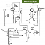
I connected the 15K resistor with a bypass cap (30uf) after L1C1. This produced 14mV of hum. Then, the 15 resistor with bypass cap (30uf) was connected after L2C2 which produces only 4mV of hum, which is un-noticeable.
Do you have a schematic how you precisely did it? First time? I remeber the ultrapath schematic which is not wjatwe talk about now...
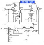
Here are the 2 schematics that I tried today. 14mA of hum and 4mA of hum. The only difference is 15K resistor (with bypass cap 30uF) is fed from C1 vs. C2.
Note: I have yet to implement the fixed bias. Also, I went with the conventional cathode bypass cap instead of ultrapath. I did not notice a difference is sound nor did it change the hum level.
Note: I have yet to implement the fixed bias. Also, I went with the conventional cathode bypass cap instead of ultrapath. I did not notice a difference is sound nor did it change the hum level.
Attachments
Last edited by a moderator:
The secondary on the IT is not open, it is grounded. It won't work it is not grounded (or referenced)...
Ian
I see the only thing across the secondary of the IT as the input C of the output tube. Wouldn’t that mean that the primary L of the IT would make up the bulk of the load at low frequencies?
Why do you use 2 bleeder resistors? One parallel to the first cap is enoughHere are the 2 schematics that I tried today. 14mA of hum and 4mA of hum. The only difference is 15K resistor (with bypass cap 30uF) is fed from C1 vs. C2.
Note: I have yet to implement the fixed bias. Also, I went with the conventional cathode bypass cap instead of ultrapath. I did not notice a difference is sound nor did it change the hum level.
You do not connect the IT secondary to the ground. only to the regulator ! Otherwise you shorten the reg. And have still ground potential on the grid.
Same for your driver tube. the 100k resistor pits your grid to ground potential while you want a negative grid potential. I have not worked with batteries, but I guess it comes between the resistor and ground.
And Rod wanted not 30uF infront of the reg but 100uf-1k-100uF CRC supply...
But I would simply put two cree sic diodes on the cathode of the driver tube. See Ale bartolas page. No messing around with batteries necessary.
Correct. The problem is that his power supply delivers too high B+ to do fixed bias.
This is why in my very 1st post I asked if his power transformer maybe had some other HT secondaries...
Sorry I have not been on this forum in the last week or so.
Here are the 2 schematics that I tried today. 14mA of hum and 4mA of hum. The only difference is 15K resistor (with bypass cap 30uF) is fed from C1 vs. C2.
Note: I have yet to implement the fixed bias. Also, I went with the conventional cathode bypass cap instead of ultrapath. I did not notice a difference is sound nor did it change the hum level.
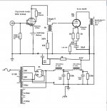
Ohm's law tells me that you are running the C3g at nearly 20mA, if that dropping resistor is only 11k ohm. That is too hot for C3g.
If the dropping resistor is 15k then you are running 14.5 mA
Also, the 2nd schematic has you feeding the C3g off the 1st choke. The B+ will be cleaner after the second choke.
IMHO Fixed bias won't be an option until you get the B+ down to around 325-350V.
Even then, you will still have the problem that the IT is only 5k. So I might add "load" to it using a resistor.
The attached schematic is not perfect.. some voltages are not adjusted. but this is what I really meant in an earlier post.
Also, learning how to use Duncan Amps PSU II software will help a lot. It helps you get a good idea of the power transformer you might need to source for fixed bias.
Lastly, I don't like that mercury rectifier. You won't find one in my home. But you know that.
Ian
Attachments
Last edited:
The reason your hum goes up is that you’re taking the pre stage from less filtered power.
Also on paper three 3H chokes give a better performance than one 9H choke. Essentially you end up with a 3rd order 3H LPF compared to a 2nd order LPF.
Broskie’s aikido blog entries are interesting reading - injecting power noise in ratios to cause cancellation may be of interest.
For example taking the 4mV but then adding it earlier into the preamp stage as anti-phase that then becomes amplified and cancels.
Last edited:
Loftin-White's original schematic did PS noise cancelling in 1930's Radio News. In my opinion is the most interesting part of their design.
You can read the article here:
Loftin White Radio News 1930.pdf
Broskie forgot to reference this in his blog, which instantly caused him to lose a LOT of credibility for me.
For some reason, later Loftin-White schematics (from other sources usually) lack the noise cancelling part of the circuit. This is sad since it works rather well.
Last edited:
Here are the 2 schematics that I tried today. 14mA of hum and 4mA of hum. The only difference is 15K resistor (with bypass cap 30uF) is fed from C1 vs. C2.
Note: I have yet to implement the fixed bias. Also, I went with the conventional cathode bypass cap instead of ultrapath. I did not notice a difference is sound nor did it change the hum level.
Your schematics don't show earthing of the filament supply of the C3g. Is it earthed in real life or? If not, this could contribute to hum.
- Home
- Amplifiers
- Tubes / Valves
- Low DCR Chokes: Will it improve transients/dynamics?