Update: I have been listening over the past 24 hours, not only to my favorite chamber music but also some rock/pop at loud listening levels. I am very pleased with the changes to the amps. The drive and transient response seems much improved. Amps sound more alive. Toe tapping fun. I will likely change out the remaining C1 and C3 caps to CDE, just like I did with the C2 cap. Also, looking into going with fixed bias on the 45B. More to come. I am learning and having fun!!!
Many thanks to all who has responded. Much appreciated.
Many thanks to all who has responded. Much appreciated.
You will see that the CDE improve your amp each time.
Just one hint: There have been a lot of suggestions on changes on your circuit in this thread. Just do only one after the other and take your time or you will end up in the woods. Its the learning experience and the judgement that you clearly see what does what to your system...and that needs time. only one parameter change at a time...I took a couple of years only for the psu...changes in SQ have been massive, not even touching the circuit. But the best sounding PSU gives its signature to anything you have after it...its the old Linn LP12 Logic: when the front end sounds bad, it will sound bad overall, no matter what you try later. And the PSU is the front end. An amorphous power transformer sounds so much better than normal HIb stuff...but you need dedicated guys like 50Ae to get something like this in your hands to try (he is now winding for me nano powerxformer).
Ot os a paradigmn shift though: Typically people first design their circuit and than ask what psu they need. Actually I build a PSU which can delivery any voltage I want with all reasonable current variations, so I am now independant to try tubes or circuits, no matter what they are. Be it a 300b at 400V or a 845 at 1000V.
I think the guys from Lyra used amorphous as well...but some people here found this as well...Amorphous core in the toroidal power supply transformer for the ultimate audio
Last edited:
Remove C2? Is this what you are suggesting (see attached)? Or, do you want to have the 11K connected directly to the C3g Anode?
Sorry for my delayed response... unhook the 30uF 900V cap and see how it sounds.
It's still not really ideal if you do this, but it makes the 11k Ohm resistor part of the C3g load. Sure, there will be some increased instability, but it should also work and should be louder.
You could try an smaller RC dropping network than the 11k one, but keep a load resistor in series with the 5k IT choke (if you like it).
Best regards
Ian
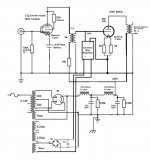
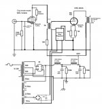
Gyrator loaded VAS stage.
This looks similar to some very successful amplifiers I have built. 🙂
@ soulmerchant, since the secondary of the IT transformer is open isn't the input tube loaded by the inductance of the the IT primary rather than the arbitrary 5K printed on the schematic? I suppose it would be easy enough to check if it was working with a frequency sweep.
The secondary on the IT is not open, it is grounded. It won't work it is not grounded (or referenced).
Now, there is always a static resistance associated with coupling transformers (like IT's and OT's). It should always be quite LESS than the inductance... You can calculate it using Ohm's law. This is not the same a load though. The load is 5k in this case since that is what the amplified AC signal will "see".
For resistors it is simple. The AC load is the same as the DC load. 🙂
Frequency response is something very important to consider too. You can easily lose high frequency response if the source doesn't have low enough output impedance to drive the input capacitance. Then your amplifier kind of sucks...
You might think, hey.. I am using and IT so I will be fine. But capacitances are reflected through the IT, and even the BEST IT's have parasitic losses. So IT's need to be used in a careful way. If you try to use anything higher than 1:1 you need to do some maths to make sure you won't be unhappy with your result. Btw - it is possible to use IT's in configurations such as 2:1 and 4:1 - this can work well in the correctly designed circuit.
Ian
Last edited:
Sunday laboratory results:
Ian - I removed the 30uF cap (c3) leading to the C3g. Not much change in sound. A bit louder, but bass was overloading in my room. Not sure if this is a function of my room or the amps.
Then, I removed the ultrapath cap on the 45B and the 30uF c3 cap was removed as well. This really made a nice improvement in the 200+ hz range. Everything become cleaner and more transparent. The bass was thinner, but better defined and did not overload the room. This tells me that the bypass caps are detrimental to the sound, in my opinion in my system in my room. So, don't flame me.
So, how do I keep the bass full and remove the caps from the signal path?
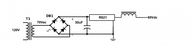
1. Fixed Grid bias. This eliminates the finals cathode bypass cap. I need 69V of bias on the 45B. I have an unused 70Vac secondary on the power transformer. The attached schematic shows the conceptual AC-DC rectification with cap, Rdropper and choke. First question: does this schematic look correct?
Vdc = 70Vac * 1.414 = 99V - Vdrop = 99V - 1.4V = 97.6Vdc
IF the calculation above is correct and my target is 69Vdc, then the Rdropper should be R = 28.6 / 46mA = 621 ohms.
I have no idea how to size the choke. Help!
2. Do I really need the c3 30uF cap? I did not hear much of a change with or without it. Ultimately, a dedicate power supply for the driver tube would be ideal. But until then, what if a choke was used after the 11K dropping resistor?
3. Move the C3g driver -2.6V batter bias to the grid instead of the cathode.
Let's keep this going and fun!
Ian - I removed the 30uF cap (c3) leading to the C3g. Not much change in sound. A bit louder, but bass was overloading in my room. Not sure if this is a function of my room or the amps.
Then, I removed the ultrapath cap on the 45B and the 30uF c3 cap was removed as well. This really made a nice improvement in the 200+ hz range. Everything become cleaner and more transparent. The bass was thinner, but better defined and did not overload the room. This tells me that the bypass caps are detrimental to the sound, in my opinion in my system in my room. So, don't flame me.
So, how do I keep the bass full and remove the caps from the signal path?
1. Fixed Grid bias. This eliminates the finals cathode bypass cap. I need 69V of bias on the 45B. I have an unused 70Vac secondary on the power transformer. The attached schematic shows the conceptual AC-DC rectification with cap, Rdropper and choke. First question: does this schematic look correct?
Vdc = 70Vac * 1.414 = 99V - Vdrop = 99V - 1.4V = 97.6Vdc
IF the calculation above is correct and my target is 69Vdc, then the Rdropper should be R = 28.6 / 46mA = 621 ohms.
I have no idea how to size the choke. Help!
2. Do I really need the c3 30uF cap? I did not hear much of a change with or without it. Ultimately, a dedicate power supply for the driver tube would be ideal. But until then, what if a choke was used after the 11K dropping resistor?
3. Move the C3g driver -2.6V batter bias to the grid instead of the cathode.
Let's keep this going and fun!
Attachments
Keep in mind you must power on in 2 steps at first the grid supply and heater of the mercury rectifier and later B+
Yes, I have 2 on/off switches. 1. filaments & 2. B+
Another idea I have is to replace the C3g with an 801A driver running at the same Vdc as the 45B ~420Vdc. This would eliminate the 11K dropper (and associated bypass cap). Thoughts?
Another idea I have is to replace the C3g with an 801A driver running at the same Vdc as the 45B ~420Vdc. This would eliminate the 11K dropper (and associated bypass cap). Thoughts?
Be aware that a choke in the bias supply does not make too much sense as the current in this circuit is minimal, maybe 2-3mA. Dont make your life too complicated. You want a normal voltage divider with some potentiometwr in the beginning. like this one 1set Tube Amp negative Grid Bias Netzteilleiterplatte montiert 4 Kanal fur PP Eierschalen | eBay
Later you might want to upgrade to rod colemans bias regs or pete millets shunt bias regs.
The 801A has only a gain of 8...vs. the gain of 50 you have at the moment...so it depends where your volume setting is at the moment...but I would guess you may need two 801A stages...
Later you might want to upgrade to rod colemans bias regs or pete millets shunt bias regs.
The 801A has only a gain of 8...vs. the gain of 50 you have at the moment...so it depends where your volume setting is at the moment...but I would guess you may need two 801A stages...
Last edited:
You connect the negative end of his bias reg to the other end of the secondary of the IT which does not go to the grid. So, you do not ground the It anymore on the secondary.
like shown here...Ergebnis der Google-Bildersuche
Other than that, Rod suggests a pretty simply 100uF-1k-100uF supply as the raw supply...have a look into the schematic in the manual.
No, you need clean DC I guess, but that is a simply task, no ?
like shown here...Ergebnis der Google-Bildersuche
Other than that, Rod suggests a pretty simply 100uF-1k-100uF supply as the raw supply...have a look into the schematic in the manual.
No, you need clean DC I guess, but that is a simply task, no ?
Last edited:
You do not connect the IT secondary to the ground. only to the regulator ! Otherwise you shorten the reg. And have still ground potential on the grid.
Same for your driver tube. the 100k resistor pits your grid to ground potential while you want a negative grid potential. I have not worked with batteries, but I guess it comes between the resistor and ground.
And Rod wanted not 30uF infront of the reg but 100uf-1k-100uF CRC supply...
But I would simply put two cree sic diodes on the cathode of the driver tube. See Ale bartolas page. No messing around with batteries necessary.
Last edited:
Remind me about the 15k resistor infront of the primary of the IT...was this meant only for voltage dropping purpose? Then it should have a PSU cap behind it and attached to the first stage of your LClC I guess.
Currently it mixes up transformer loading and resistor loading and presents a high impedance psu to the transformer while we did everything to have a low DCR ib the psu (what was the name of this thread again?). This is a dynamic killer.
Currently it mixes up transformer loading and resistor loading and presents a high impedance psu to the transformer while we did everything to have a low DCR ib the psu (what was the name of this thread again?). This is a dynamic killer.
And I miss fhe 0.33uF to 0.5uF high quality cap ibfront of the first choke...give it a try, you might be surprised.
And I miss fhe 0.33uF to 0.5uF high quality cap ibfront of the first choke...give it a try, you might be surprised.
Surely this causes the psu choke to be a full swing choke? If it’s not been designed for it, it’s going to get very warm.
No. The opposite is the case. It is cooler as the ripple voltage VPp aceoss it gets smaller and the sttess level for the choke is less. It is a step towards CLC without causing a Voltage increase. And CLC is a lot less stressfor the choke (but sounds very different).
No luck with this cap, I prefer L inputAnd I miss fhe 0.33uF to 0.5uF high quality cap ibfront of the first choke...give it a try, you might be surprised.
Remind me about the 15k resistor infront of the primary of the IT...was this meant only for voltage dropping purpose? Then it should have a PSU cap behind it and attached to the first stage of your LClC I guess.
Currently it mixes up transformer loading and resistor loading and presents a high impedance psu to the transformer while we did everything to have a low DCR ib the psu (what was the name of this thread again?). This is a dynamic killer.
Blitz - the 15K is a voltage dropping resistor. I tried moving the 15K (including the bypass resistor) to the first stage of LCLC, but it caused too much hum.
- Home
- Amplifiers
- Tubes / Valves
- Low DCR Chokes: Will it improve transients/dynamics?