50AE - you can't argue with these people, they feel approved when you answer. Don't feed the trolls.
Soulmerchant is right: wrong 45B plate current values on schematics and nobody has seen it.
banpuku - the cathode R-values on you schematics are confusing. post 1: R-cathode 45B = 1K versus post 142: R-cathode 45B = 1.8K. Do it right.
Respect the 80 percent power limit dissipation of tubes. If you go near 100 percent they won't last long.
Post1: 45B _ 61V / 1K = 61mA x 349V = 21.29 Watt, limit is 22 Watt, _ tube C3g _ 16mA x 210V = 3.36 Watt, limit is 3.5 Watt
You want to replace C3g with a 1:8 silver input transformer + 801A driver. You are using a autoformer as volume control. Autoformer + 1:8 step-up to drive the 801A is a difficult task. 50AE may answer what is useful.
You want to use the 5K Slaggle interstage: the 801A has rp of 5K _ no match. You can use the 46 in triode as driver + a direct coupled input tube.
This amp concept: diyaudio.com/forums/tubes-valves/47457-10-15-mu-dht.html _ Look at post 9.
Tube 814A needs A2 + source follower drive for decent output power.
Ask Rod Coleman for best bias circuit in your amp. You need 2 x 70VAC windings for 2 separate bias psu's. No single psu for both channels. Fixed bias = no cathode resistor on 45B, your HV will be much higher - consider this.
Remember when using an 1:8 transformer that:
-The capacitance connected at the secondary, for example the 801A's Miller is reflected 64 times on the primary. This requires a low impedance driver thought for this capacitance.
-The leakage inductance such transformer has an extreme chance of having, will resonate with the secondary's Miller capacitance, possibly close or within the audio band.
In the end it is an extremely sensitive situation that can easily lead to trouble. Not impossible, but will require careful engineering an a well though designed custom transformer.
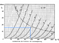
If I wasn’t big wrong in the simulation, this is the Emissionlab's recommended biasing for 45B at 5k load.
Emission Labs. Information about life time of electron tubes.
45B Recommended Single Ended operating points.
Bias Method: Auto Bias.
The 45B spice simulation is "as is", not verified with the original curves!
As you can see, even the IT loaded C3g is unable to drive this to maximum power.
Emission Labs. Information about life time of electron tubes.
45B Recommended Single Ended operating points.
Bias Method: Auto Bias.
The 45B spice simulation is "as is", not verified with the original curves!
As you can see, even the IT loaded C3g is unable to drive this to maximum power.
Attachments
The 45B in Post # 162.
495V - 87V = 408V
87V /1800 Ohms = 48mA
408V x 0.048A = 19.6 Watts
I know that the 45B is specified for 22 Watts.
If you trust that manufacturer, it will work well there.
Please let us know how long the tube lasts.
The 2A3 is rated for 15 Watts, and the larger more massive 300B is rated for 36 Watts (Western Electric's later 1950s era data sheet).
I know that if someone gave me some 45B tubes, I would not put more than 15 Watts in the plate.
Last edited:
6A3sUMMER: Check Emission Labs Factory datasheet before you post....:
Emission Labs. Information about life time of electron tubes.
Emission Labs. Information about life time of electron tubes.
The 2A3 is rated for 15 Watts, and the larger more massive 300B is rated for 36 Watts (Western Electric's later 1950s era data sheet).
EML 2A3-S dissipates up to 28 watts...
For the price of one EML 45B, I can try a few 2A3 tubes, or even two 300B tubes.
Right?
Ratings are what they are.
Note that even Western Electric changed the 300B rating from 40 Watts to 36 Watts.
Perhaps they found that not pushing a tube so hard would increase the tube life.
Oh, the JJ 2A3 is rated for 40W plate dissipation.
Find a tube that has the ratings you need, and then use it.
Just remember, Re-inventions of original tube designs are not original tubes. How about the many many filaments of the original Monoplate RCA 2A3.
Western Electric was the old champion of tube life when they built tubes for trans-oceanic underwater cables.
Oh, I originally posted on 8:09, and edited on 8:18 to add the 22 Watt 45B rating.
daanve caught my 8:09 post, but did not see my 8:18 re-edit of that post when he said for me to check the EML datasheet before posting.
I am sorry for the late correction of my post.
Timing is everything, even in music and music playback.
Last edited:
You can claim whatever you like when it's pure fantasy.What you fail to understand again and again is, in this thread a certain group of people is discussing phenomena we claim we've heard.
I don't seem to be the only one here calling you out on this BS.
It's like the latest IPCC report which restarts the pure fantasy "hockey stick" of Michael Mann, (which has been thoroughly thrown out + debunked as it's based on junk science).
You can keep coming back time and time again every 15 years with the same fantasies just like Michael Mann.
Repeating fantasies doesn't make them any more valid than they were 15 years before - assuming we forgot about them since when they came around first time.
As for our friend who posted here although I agree with much of what was said...
I have to say
My comment was more on the different magnetic properties of silver vs. copper. From Jack Elliotts page (electra print):...etc
His name is Jack Elliano, not Elliott.
Let's hope this time you succeeded understanding your expression for fantasy and BS is still a claim without proof.
Yes, highly probable you're not the only one calling me out, neither I'm not the only one with this nature of my claims.
Doesn't make a difference really. We can go on like this forever in circles. So for the sake of efficiency and personal time saving I'm out from this debate, however staying open to the thread author and followers.
If I wasn’t big wrong in the simulation, this is the Emissionlab's recommended biasing for 45B at 5k load.
Emission Labs. Information about life time of electron tubes.
45B Recommended Single Ended operating points.
Bias Method: Auto Bias.
The 45B spice simulation is "as is", not verified with the original curves!
As you can see, even the IT loaded C3g is unable to drive this to maximum power.
Very good, but you should include the supply as well. The impedance is quite high mostly from losses in Transformer and rectifier which I approximate with the 490R
Almost all of the variable current is supplied by the 50u cap, the choke has a very high impedance at audio frequencies. It delivers only the DC part. Even at 20Hz 80% come from the capacitor.

The varying anode voltage by 12Vpp will cause some more 3rd harmonic distortion.

I modelled it this way. The additional cap improves the ripple about 20dB at little extra cost. It makes a notch at 100 or 120 Hz

If you are going to present a spectrum beyond about 300-500Hz then best to model the choke better (shunt capacitance and some dampening - preferably modelled on the actual choke by making an impedance plot versus frequency).
In that #170 PS output impedance curve, bass phase changes roughly from -10º at 25Hz to -90º at 125Hz while our precious OT will furthermore add some LF phase shift. There's a point reproduction starts to loose realism, with or without the "snappiness" some are craving for. Add more poles for the loudspeakers and there you have it: a real to life reproduction system is just an illusion. Just be happy and enjoy the hobby.
Last edited:
As you can see, even the IT loaded C3g is unable to drive this to maximum power.
Nice simulation. I hinted at this in post #155. One (or maybe a few) of my amps uses a gyrator on C3g... 😉
My suggestion was for him to try using a resistive load and coupling capacitor and see how that worked.
Rough calculations suggests he could simply use the 11k ohm dropping resistor as the load. Cap couple C3g plate to the IT for now of course.
Just to see if he notices a difference...
Ian
Fixed bias = no cathode resistor on 45B, your HV will be much higher - consider this.
Yeah, that's what might make it a deal breaker. Fixed bias is worth doing, and he has an IT... so tempting!
But this will likely require a different mains transformer. This is why I simulate everything as much as possible before biting the bullet and getting the mains transformer.
soulmerchant - your post 155 - plate curves for 45B, maybe i have an idea. You were looking at ca 333V plate and -60V grid: ca 75mA.
The 2 x 50r ballance resistors for filament are parallel, so act as one 25r. 25 x 0.033 = 0.85V + 59V = yes ca 60V. But if you look at 350V, -60V grid: EmL 45B plate curves should be ca 90mA. banpuku has only 33mA ! Power dissipation: 11.55 Watt ! This is extreme low. This has nothing to do with a weak psu, its the 45B tube. His tubes are far out of specs, if his numbers are real. This may be realy bad, because the tubes look like worn out. The datas from all 3 schematics show a hugh tube deterioration over time.
I have added the schematic from post 142. I marked 2 green points there.
banpuku - please measure the DC voltage at these 2 points again and give us the values for both tubes. On post 1 you have used a 1K cathode resistor. Since post 142 you have a 1.8K cathode resistor. Confirm this. No mA values. We want to check how much your 45B's are out of specs.
banpuku - on your thread - review dave slagle interstage transformer - from Oktober 19. 2019 in post 1 there is your 45B schematic: 410V on 45B plate, 66V on 1K catode resistor. 66 / 1K = 0.66mA, Filament ballance 25r x 0.066mA = 1.65V + 66V = 67.5V on cathode, a-k: 342.5V
Look at 344V plate and -66V grid curves: ca 66mA ! Power dissipation on 45B: 22.6 Watt - max specs are 22 Watt.
At that time your tubes were ca 100 percent specs.
Go to post 1 schematic of this thread: 410V plate, 61V on 1k cathode: 61 / 1K = 61mA, Filament ballance 25r x 0.061mA = 1.5V +61V = 62.5V cathode, a-k: 347.5V, plate curves at 347.5V and -61V grid curves: ca 90mA. Instead of ca 90mA you have 61mA ! Power dissipation: 21.2 Watt.
banpuku - if you would use a class A transistor amp 2 x 10 Watt with too low power for your loudspeakers - it would not hurt the amp. But if you do this with a small SE tube amp and power hungry loudspeakers, they will eat your tubes.
A pair EML 45B cost ca 700 USD.
Other may check if i made wrong calculations here.
We were talking so much about how to tweak this amp, that we forgot to check the basics.
Attachments


We were talking so much about how to tweak this amp, that we forgot to check the basics.
Hi guys, I am going to re-check all measurements tomorrow and will post a fully verified schematic and measurements. Thanks for the continued help!
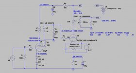
Hi team - hope all is well. I have made a few changes and would like to report the measurements and operating points.
Changes:
1. Installed a CDE 250uF cap at C2 position
2. changed the driver bias battery to 2.6V from 1.3V
3. changed the C3 dropping resistor to 15K from 10k
4. Re-installed the 83 rectifier in lieu of the 5Z3
5. changed the 100R C3g Anode resistor to a Riken 100R
B+ Measurements:
C2 = 423Vdc
C3 = 205Vdc
C3g driver
bias = 2.6Vdc
B+ at Anode: 193Vdc
calculated current = 423V-205V = 218V / 15k ohm = 14.5mA
dissipation = current * voltage = 193 * 14.5 = 2.8watts (80% of 3.2watt max)
45B
bias = 69Vdc
B+ at Anode: 415Vdc
Anode to bottom of 2x50R = 346Vdc
calculated current = 415V-346V = 69V / (15000+25) ohm = 46mA
dissipation = current * voltage = 415 * 46 = 19watts (86% of 22watt max)
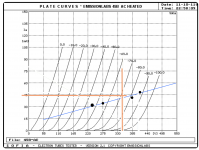
The attached schematic and tube curves reflect the items above. Note: the EML 45B plate curves have 4 operating points (black dots) that represent operating points identified by EML. These are for reference only and as you can see, my operating point (intersection of the salmon colored lines) is nearly on the blue cathode load line along with these 4 operating points.
After letting the amps run for 4 hours, I listened for an hour. The immediate change in sound was the 3D depth improved significantly. Not sure what this is attributed to, but this change was clearly an improvement. More comments on listening as the system settles and he CDE caps break-in. Per Blitz, they take a week to settle down. More to come.
Comments welcomed!
Changes:
1. Installed a CDE 250uF cap at C2 position
2. changed the driver bias battery to 2.6V from 1.3V
3. changed the C3 dropping resistor to 15K from 10k
4. Re-installed the 83 rectifier in lieu of the 5Z3
5. changed the 100R C3g Anode resistor to a Riken 100R
B+ Measurements:
C2 = 423Vdc
C3 = 205Vdc
C3g driver
bias = 2.6Vdc
B+ at Anode: 193Vdc
calculated current = 423V-205V = 218V / 15k ohm = 14.5mA
dissipation = current * voltage = 193 * 14.5 = 2.8watts (80% of 3.2watt max)
45B
bias = 69Vdc
B+ at Anode: 415Vdc
Anode to bottom of 2x50R = 346Vdc
calculated current = 415V-346V = 69V / (15000+25) ohm = 46mA
dissipation = current * voltage = 415 * 46 = 19watts (86% of 22watt max)
The attached schematic and tube curves reflect the items above. Note: the EML 45B plate curves have 4 operating points (black dots) that represent operating points identified by EML. These are for reference only and as you can see, my operating point (intersection of the salmon colored lines) is nearly on the blue cathode load line along with these 4 operating points.
After letting the amps run for 4 hours, I listened for an hour. The immediate change in sound was the 3D depth improved significantly. Not sure what this is attributed to, but this change was clearly an improvement. More comments on listening as the system settles and he CDE caps break-in. Per Blitz, they take a week to settle down. More to come.
Comments welcomed!
Attachments

Last edited by a moderator:
banpuku - what is the value of the cathode resistor of 45B ? On schematic 1.8K, but your calculation is 1.5K. Your measurement is again confusing.
Measure this: look post 175 schematic with 2 green dots on 45B;
1. measure from ground to lower dot (bottom of 2 x 50r)
2. measure from ground to cathode (filament) of 45B. Cathode is not bottom of 2x 50r.
3. measure from ground to anode 45B (top green dot)
Give us this 3 values.
Measure this: look post 175 schematic with 2 green dots on 45B;
1. measure from ground to lower dot (bottom of 2 x 50r)
2. measure from ground to cathode (filament) of 45B. Cathode is not bottom of 2x 50r.
3. measure from ground to anode 45B (top green dot)
Give us this 3 values.
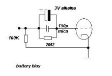
banpuku - in your schematic you have the minus of the battery at cathode of C3g. Wrong. The tube would work know with +2.6V positive bias.(grid current) Even if you have the + on cathode, battery on cathode doesn't sound good.
Go back to 2 x LED for +2.6V bias. Cathode of LED on ground.
Do a search for battery bias. This just a example, you need a coupling cap at input.
Go back to 2 x LED for +2.6V bias. Cathode of LED on ground.
Do a search for battery bias. This just a example, you need a coupling cap at input.
Attachments
- Home
- Amplifiers
- Tubes / Valves
- Low DCR Chokes: Will it improve transients/dynamics?