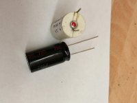
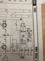
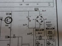
I was wrong! 😱 The positive side of the new 2000uF capcitor should be connected to chassis earth (as shown in your circuit diagam). The red dot on the original 2000uF capacitor is, of course, the positive terminal.
Re your new capacitors, if the short lead is -, then the long lead has to be +.
Will look back at photos to see what you mean about "goes to the red insulation on the capacitor".
Re your new capacitors, if the short lead is -, then the long lead has to be +.
Will look back at photos to see what you mean about "goes to the red insulation on the capacitor".
Thanks. So far, so good then.
The +ve (red wire) on the rectifier, does that go to the long lead on the new capacitor?
Rob
The +ve (red wire) on the rectifier, does that go to the long lead on the new capacitor?
Rob
If you've bought the new rectifier as advised, then connect + terminal of rectifier to + terminal (the long lead) on the capacitor.
Okay. And does the earth tag on the centre of the rectifier also go the +ve terminal of the capacitor (also +ve of rectifier)?
The rectifier mounting bolt provides the earth connection. Connect the tag on the bolt to the positive terminal of the cap. No other earth connection is required.
The positive terminal on cap should also be connected to the positive terminal on rectifier.
In other words, make the connections as they were originally implemented.
The positive terminal on cap should also be connected to the positive terminal on rectifier.
In other words, make the connections as they were originally implemented.
Last edited:
Hi Galu,
Got it now 🙂
I will have to finish off the connections tomorrow morning now, as my wife is calling me (we have friends round in ten minutes time).
I'll post a picture once I've got them all done - It's just the earth connection to go.
Thanks for all your help, Rob
Got it now 🙂
I will have to finish off the connections tomorrow morning now, as my wife is calling me (we have friends round in ten minutes time).
I'll post a picture once I've got them all done - It's just the earth connection to go.
Thanks for all your help, Rob
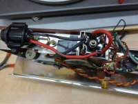
Up nice and early, and I've done the wiring how I believe it has been explained to me, and how it should be. Please see attached pictures, and labelled up circuit diagram.
I didn't have cable in all the original colours (red, and black), so to keep consistency I've sleeved the cabling the original colours.
The red lead goes to the +ve on the big (2200uF) capacitor, then to the earth tag. The twisted brown pair of wires come from the motor/transformer.
I didn't have cable in all the original colours (red, and black), so to keep consistency I've sleeved the cabling the original colours.
The red lead goes to the +ve on the big (2200uF) capacitor, then to the earth tag. The twisted brown pair of wires come from the motor/transformer.
Attachments

Yee haw! The hum has gone 🙂 Happy Days!!
I'm going to get on with cleaning it all up now, and checking the mechanicals over.
The outside casing is looking a bit dull and pitted on the top, but I'm not sure whether to leave it like that and have a bit of a vintage Patina, or investigate paints to put on the vinyl covering. I'm not sure what sort of paint would be needed though.
The outside casing is looking a bit dull and pitted on the top, but I'm not sure whether to leave it like that and have a bit of a vintage Patina, or investigate paints to put on the vinyl covering. I'm not sure what sort of paint would be needed though.
Try a visit to your local guitar/amp shop.
They have methods for renovating ole amps and speakers with vynal coverings.
Also car interior renovators may be able to help.
Andy
Well done!
I also got up early, but went back to bed again!
It is Sunday after all. 😉
Re vinyl: I would keep it vintage. Amazing what a difference a little soap and water makes.
I also got up early, but went back to bed again!
It is Sunday after all. 😉
Re vinyl: I would keep it vintage. Amazing what a difference a little soap and water makes.
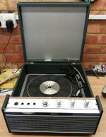
Here's a pic of what it looks like after I've cleaned it up a bit.
The bit that's poor quality is the top of the cabinet, but that's not shown in the picture.
I think there may still be a problem with the mechanical movement of the arm, but I'll look into that later.
Thanks all. Rob
The bit that's poor quality is the top of the cabinet, but that's not shown in the picture.
I think there may still be a problem with the mechanical movement of the arm, but I'll look into that later.
Thanks all. Rob
Attachments
.
Looks pretty good to me.
I would not attempt any more cleaning.
Be careful of the printed letters as they come off very easily.
Some auto-changer mechanisms appear "stiff" but that is the nature of the beast.
Clean off any old grease and renew with a smear of vaseline.
Andy
.
Looks pretty good to me.
I would not attempt any more cleaning.
Be careful of the printed letters as they come off very easily.
Some auto-changer mechanisms appear "stiff" but that is the nature of the beast.
Clean off any old grease and renew with a smear of vaseline.
Andy
.
Last edited:
I can't say it was just replacing the rectifier that resolved the buzzing, as I replaced the capacitor across it and the other electrolytic capacitors all at the same time.
I've sorted out the mechanical bits that were sticking now, which was mainly the steel spindles that go through the large alloy cam mechanism. I've also cleaned up as much of the other mechanicals I could and applied fresh grease.
However I still have a couple of other issues -
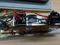
(1) The large steel wheel with rubber on its edge, that takes power from the various size motor spindles (sets record speed), and applies it to the inside of the platter isn't getting good drive to turn everything. It just about plays a record at the correct speed, but you can see it's struggling, especially when it needs to move the arm. I presume the rubber has hardened with age. Is there a known good fix for this that's simple, and isn't too expensive? I was thinking that maybe shortening a spring, or putting some self vulcanising rubber tape around the existing wheel may help, but I'm sure others have come before me and no some solutions.
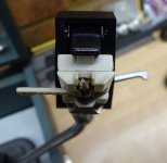
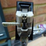
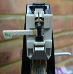
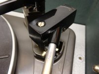
(2) The needle fell out when I turned the deck, and it got caught. This was a thin alloy shaft about 1 cm long with a needles on either side. I've pushed it back into the silicone sleeve and it now picks up and works again. However the cartridge can sometimes be heard rubbing on the surface of the record, so maybe I've done something wrong. Or could it be that the silicone bit that supports it has lost strength over time, or there's too much pressure being applied? I'm not sure how you set up tracking force on these arms.
Hopefully the pictures attached will also help.
Thanks in advance, Rob
I've sorted out the mechanical bits that were sticking now, which was mainly the steel spindles that go through the large alloy cam mechanism. I've also cleaned up as much of the other mechanicals I could and applied fresh grease.
However I still have a couple of other issues -
(1) The large steel wheel with rubber on its edge, that takes power from the various size motor spindles (sets record speed), and applies it to the inside of the platter isn't getting good drive to turn everything. It just about plays a record at the correct speed, but you can see it's struggling, especially when it needs to move the arm. I presume the rubber has hardened with age. Is there a known good fix for this that's simple, and isn't too expensive? I was thinking that maybe shortening a spring, or putting some self vulcanising rubber tape around the existing wheel may help, but I'm sure others have come before me and no some solutions.
(2) The needle fell out when I turned the deck, and it got caught. This was a thin alloy shaft about 1 cm long with a needles on either side. I've pushed it back into the silicone sleeve and it now picks up and works again. However the cartridge can sometimes be heard rubbing on the surface of the record, so maybe I've done something wrong. Or could it be that the silicone bit that supports it has lost strength over time, or there's too much pressure being applied? I'm not sure how you set up tracking force on these arms.
Hopefully the pictures attached will also help.
Thanks in advance, Rob
Attachments
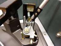
1. First step is to clean the edge of the idler wheel and the driven surface of the platter with alcohol. If that doesn't work, roughen the rubber with fine emery paper. Replacement idler wheels are to be found on auction sites.
2. I presume this is the original stylus you are describing. It should be replaced as a matter of course, but the entire cartridge may need replacing if the stylus suspension has deteriorated. How to adjust the tracking force is described in the Garrard 3000 manual: https://www.google.com/url?sa=t&rct...s-Manual.pdf&usg=AOvVaw2drZlWJsEkauHLAPx-cpxy
2. I presume this is the original stylus you are describing. It should be replaced as a matter of course, but the entire cartridge may need replacing if the stylus suspension has deteriorated. How to adjust the tracking force is described in the Garrard 3000 manual: https://www.google.com/url?sa=t&rct...s-Manual.pdf&usg=AOvVaw2drZlWJsEkauHLAPx-cpxy
- Home
- Amplifiers
- Solid State
- Loud buzzing on Ferguson 3020/Garrard 3000 Vintage Record Player