This is basically Alan Kimmel Fig.4 Mu follower circuit.
http://www.fetaudio.com/wp-content/uploads/2003/09/Mu-Stage.pdf
Art
Wich takes us full circle to the schematic that I started the thread with 🙂
Audiohead: have you built it? Any expriences with it in general and tube alternatives in specifically?
Have you thought about using CCS at the lower tube's cathode?
What would be a good way to make the lower part into a differential pair? I am not too happy with the solution in Kimmel's article that introduces a dedicated voltage source for the second triode's plate.
Cheers!
PS: how do you guys choose driver gain based on the _nominal_ output of the source? Should we be able to reach full power at nominal output or is there some standard/proven dB value above nominal (say +10dB) at which one would normally drive the output stage to full power?
Last edited:
to agent
Is not possible to call it tube amplifer, it is a mix of sand and vacuum, plus ( maybe an incident), a OT.
I see a lot of these strange and unnecessary circuit around tube.
Most of them are mutuated from simulation and, in rare cases, put on lab.
And some people insists with the results of these simulation with a simulated measurement !
As if you can simualte an real OT!
I wrote about AN Kit One as a perfect example of a 300B s.e. tube amp.
The circuit is simply, efficent and easy to build.
The difference is mainly done by OT and they cost a lot of money.
Many people think to resolve the issue of OT just only put down these strange mix of components.
Walter
to Agent
how can call it a tube amplifier?
Walter
🙂 It's a mystery to me that everyone gives pentodes a wide berth and then goes for silicon without restraint.
to euro21
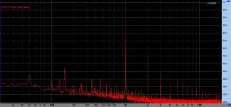
This is the reason we see a lot of harmonisc on your FFT
Walter
Really?
D3a driver, 70VRMS.
Attachments
to agent
I wrote about AN Kit One as a perfect example of a 300B s.e. tube amp.
The circuit is simply, efficent and easy to build.
The difference is mainly done by OT and they cost a lot of money.
Many people think to resolve the issue of OT just only put down these strange mix of components.
Walter
I googled. this one?

Upgrade Audionot kit 1
🙂 It's a mystery to me that everyone gives pentodes a wide berth and then goes for silicon without restraint.
Agreed. D3a is probably a good driver for 300B. There is always the classic WE310A/WE328A. But, they are all priced from pricey to ridiculous.
Last edited:
The amplifier was tested on a test bench and the measured voltage was 200v peak to peak or 70v RMS for 8w and THD was also measured for this situation with a REDFORD distortion meter and additionally with a sound card with ARTA softwarePopa Marius:
Have you actually built this driver circuit you posted?
Is the Vout 70v rms, peak or peak to peak?
THD+N figure posted is measured at what output level?
Is the THD+N figure shown on the schematic measured value or simulated?
Art
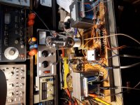
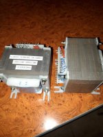
We have temporarily replaced the tube driver with a transformer identical to the output transformer under the conditions shown in the picture and with this data you can desgn the optimal driver for 300b, what do you think ?
1w=1,35% THD
2w=1,68%
3w=2,01%
4w=2,31%
5w=2,56%
6w=2,79%
7w=3,05%
8w=3,25%
9w=3,76%
10w=5,72%
1w=1,35% THD
2w=1,68%
3w=2,01%
4w=2,31%
5w=2,56%
6w=2,79%
7w=3,05%
8w=3,25%
9w=3,76%
10w=5,72%
Attachments
Last edited:
Hi Popa:
Thanks for the info.
I am working on a 6E5P shunt cascode driver circuit per Rod Coleman and Bartola published designs.
I will post my eval. results when I finish. Fitting The required heatsinks and multiple power supplies/transformer on one chassis is a royal pain in the a$$.
But I am having fun doing it. I will keep you guys posted.
Art
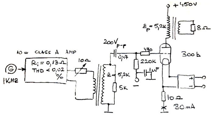
Is the equivalent of a tube driver , in my opinion, ideal. The level of attack required for the final tube is easily obtained with extremely low THD and a low impendance, basically the power tube is put in a position to show everything it can and therrefore can help when designing a real tube driver. It should be close to the power/THD measurements shown in the table in the previous post
Attachments
Not agree.
First of all you have to understand if the OT with 5k ha some resonance on high frequency and a sufficent L at low frequency
At this link you can read something around the test of OT trafo
OPT Characterization
For a real tube driver you can simply use a socket with som e components ad a HT supply.
In SRPP , the 5687 is good, the 6H30 is more linear, less or more same gain, also the 6N6 soviet
In both cases low Zout, great swing.
Same for 7044, rare.
Just ahead a simply gain stage; as AN Kit one.
No IT, a bad solution.
Walter
I've tried to wrap my head around how the mu-stage could look like with a differential input to drive a 300B output stage. I don't yet totally understand everything that I'm doing. I'll post this here and maybe one of you is kind enough to point out all the things that are wrong with it.

The resonance of the transformer is at 78 Khz and the frequency 22hz/-1dB-52Khz/-1dB but these are not relevant in this case because the practical "simulation" from the scheme proposed by me is done at 1Khz. A real driver with tubes must to approach these results and this is the purpose of this experiment, you probably dit not understand this...Not agree.
First of all you have to understand if the OT with 5k ha some resonance on high frequency and a sufficent L at low frequency
At this link you can read something around the test of OT trafo
OPT Characterization
For a real tube driver you can simply use a socket with som e components ad a HT supply.
In SRPP , the 5687 is good, the 6H30 is more linear, less or more same gain, also the 6N6 soviet
In both cases low Zout, great swing.
Same for 7044, rare.
Just ahead a simply gain stage; as AN Kit one.
No IT, a bad solution.
Walter
Attachments
- Home
- Amplifiers
- Tubes / Valves
- Looking for a 300b SE design