Hi,
Having sucesfully completed my first KT88 based PP amp this year, I feel the urge of trying to go for a purely single ended triode design as my next project. 300B based preferrably. I'm not keen on too much iron in the signal path, so interstage transformers or mandatory input transformers are a no-go.
I am looking at a design I stumbled across a while back that I set up in LTSpice to learn about that I find quite compelling. It would be great to hear from you guys if a) anything raises red flags for you in that circuit and b) if you have other recommendations of a somewhat proven design that I should look at...

Cheers,
Lars
Having sucesfully completed my first KT88 based PP amp this year, I feel the urge of trying to go for a purely single ended triode design as my next project. 300B based preferrably. I'm not keen on too much iron in the signal path, so interstage transformers or mandatory input transformers are a no-go.
I am looking at a design I stumbled across a while back that I set up in LTSpice to learn about that I find quite compelling. It would be great to hear from you guys if a) anything raises red flags for you in that circuit and b) if you have other recommendations of a somewhat proven design that I should look at...
Cheers,
Lars
hello Lars,
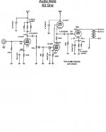
The driver looks too complex, and C18 will be reverse biased (you don't need it)
If you have a pentode to hand, (EL84, 6BW7, C3m, 6П15П, SV83) you can build a 300B driver that has excellent sound -- far better than the usual 6SN7 drivers.
The drawing is Thorsten Loesch's «Legacy»
The driver looks too complex, and C18 will be reverse biased (you don't need it)
If you have a pentode to hand, (EL84, 6BW7, C3m, 6П15П, SV83) you can build a 300B driver that has excellent sound -- far better than the usual 6SN7 drivers.
The drawing is Thorsten Loesch's «Legacy»
Attachments
A 300b SE amp can sound marvellous, and so there are plenty of versions in existence. I agree with you that 2-stage is the way to go. And while the 300b stage is relatively straightforward, everything about the sound you will get depends on the valve you chose for the input. Unless you have very sensitive speakers, you will want a valve with a mu of at least 30. You have the added option of a pentode stage or a cascode, both of which have fans. See Rod's suggestion above and Stephe's YouTube videos on a 6SN7 cascode, but I believe that good sound can also be achieved with a single true triode or pentode wired as triode.
I agree with you about avoiding an interstage - in my 300b SE experimental builds I preferred a plate choke and teflon coupling cap for which I use a couple of Russian FT-2 to make 0.2uF. Suitable plate chokes are Lundahl LL1668 and Hammond 193a. I also tried Ale Moglia's gyrator and a plain resistor load which are further options. For the gyrator see many designs on the Bartola Valves website. You can also use a further valve as an anode load, as in the design you provided. If you use a cathode bypass cap, I recommend a DC Link cap from Kemet, Oscon, Vishay etc, the best sound I achieved.
But which valve do you choose for the input? Big question. I already tried the 6N1P and found the sound OK but rather mediocre, so I'd continue looking. There are several fans of D3a and C3g in triode plus many other pentodes wired as triodes. The issue you run into is oscillation with high mutual conductance (S) valves so be prepared to play around with ferrite beads. There are double triodes like 6922 or 12AT7 but if you can find a single true triode you may get better sound. I would look at the EC86 or Russian 6S4P or 6S3P for starters. Otherwise you'll find a range of pentodes in triode on several threads.
There are multiple threads on SE 300b amps here - you could spend a whole morning reading them, or even a whole day since there are some long threads. Hopefully you'll get some good answers here since there are many of us using 300b amps.
.
Last edited:
Great insights. So input/driver stage research is something I'll be spending some time on.
I have built my phono pre with a symmetrical (XLR) outputs (using LL1527XL transformers) so it would probably make sense to build an input that can leverage a symmetrical signal by offering good CMMR.
I'd also need the sensitivity of the input to be a bit on the higher side as I don't plan on using a dedicated line stage between the phone pre and thge power amp.
The phono pre has an output impedance around 300 ohms and delivers 40dB (MM) to 60dB (MC) of gain so I'd be looking at a nominal output level around 0.3 to 0.4 V_RMS to feed the power amp.
My speakers deliver around 88db (2,83V/1m) which seems pretty much at the low end of what a 300b is useful with - (more efficient speakers are on the future projects list). So I do need the ability of the input stage to fully utilize the output tubes...
Good to hear from you, Euro21. So for larger gain what do you suggest - an input transformer, a cascode or something else? I can see the virtue of avoiding a further line stage. It would be a compromise to use a 6SL7 or something like that and maybe that wouldn't be enough gain either.
A note about specifying phono signal levels: before digital levels imposed a hard full-scale upper limit, analog levels were referenced to a 0VU level, an agreed upon but not physically limited level. For phono this became 5cm/s horizontal modulation, and later 5cm/s modulation of each channel, a 3dB difference. This is the level at which phono cartridge sensitivity is specified.
Actual peak modulation levels are consistently larger than 0VU by at least 10dB, occasionally 20dB and worst case 30dB. This larger number is the actual peak output from the cartridge, and scales your amplifier's drive signal up proportionally.
All good fortune,
Chris
Actual peak modulation levels are consistently larger than 0VU by at least 10dB, occasionally 20dB and worst case 30dB. This larger number is the actual peak output from the cartridge, and scales your amplifier's drive signal up proportionally.
All good fortune,
Chris
an input transformer, a cascode or something else?
The general problem is using such VAS and driver stage, which does not degrade the power stage capabilies.
The limiting factor of power stage is tube-OPT pair ... mostly the OPT (if matched tube used), so for example the frequency and phase transfer is usually a problem.
The other problem is the driver stage output swing capacity -at enough large current- with low THD ... as small as possible .. and -for me- at least 3dB headroom. These criteria suppose enough high B+ (swing peek+headroom+tube minimum requirement DC etc.)
Input transformer:
Good high impedance SUT is expensive toy, especially if it has more than 1:2 gain. Over it the FR limited.
The "commercial" 600R input SUT driving (various previous stages output capacity!) is almost impractical ... if you don't use specially (correctly!
 ) designed preamp.
 Cascode:
I'm -also- not a fan of multiplied VAS stages, but in this case the limiting of tube gain makes it worth considering.
A note about specifying phono signal levels: before digital levels imposed a hard full-scale upper limit, analog levels were referenced to a 0VU level, an agreed upon but not physically limited level. For phono this became 5cm/s horizontal modulation, and later 5cm/s modulation of each channel, a 3dB difference. This is the level at which phono cartridge sensitivity is specified.
Actual peak modulation levels are consistently larger than 0VU by at least 10dB, occasionally 20dB and worst case 30dB. This larger number is the actual peak output from the cartridge, and scales your amplifier's drive signal up proportionally.
All good fortune,
Chris
Yep. That' pretty much what I'm looking at. The phono stage delivers ~0.4VRMS for 1 kHz @ 5 cm/sec. IIRC 50cm/sec is the theoretical maximum which is to be expected on a record; so +20 dB or 4VRMS. That's 5.7VP as the theoretical max signal level at the input.
I think I would want to build the input in a way where the amp is maxed out at maybe +15 dB above nominal signal level. I'd rather have the option of having a bit more reserve for a recording that is one the quiet side of the spectrum. I can still dial down the volume for the loud stuff. So I would be aiming to have maxium power at 3,18VP.
The 6N1P (6DJ7/ECC88) and EL83/SV83 (or EL84, 6P15P) input stage fits pretty well into that range
I that reasonable?
Not quite sure whether a different input/driver topology would work better with a symmetricasl input then the SRPP based mu-stageused in the design I posted (see http://www.fetaudio.com/wp-content/uploads/2003/09/Mu-Stage.pdf - fig. 6 shows a variant with differential inputs - he also mentions that using a MOSFET SF instead of a pentode CF might be even better as it represents an even greater impedance for the triode(s). It runs counter to the idea of the amp being very "pure" though and I know that many here will cringe at such endavors - I am somewhat in the same camp but I do realize that it may not be the most rational position)
Last edited:
0.4VRMS of signal into a integrated 300B amp is going to be a real challenge. I know my 6SN7 cascode design wouldn't be happy with that! Is there anyway to get your phono pre up to normal line levels? As others noted, it's going to require a lot of gain to get a driver to have the swing/current a 300B needs and still also sound good.
Please note you aren't going to be able to sim what am amp will actually sound like, and I've seen a few 300B sims recently that look fine in the simulation, and end up with major distortion when constructed.
Skunkie Designs 300B
Please note you aren't going to be able to sim what am amp will actually sound like, and I've seen a few 300B sims recently that look fine in the simulation, and end up with major distortion when constructed.
Skunkie Designs 300B
0.4VRMS of signal into a integrated 300B amp is going to be a real challenge. I know my 6SN7 cascode design wouldn't be happy with that! Is there anyway to get your phono pre up to normal line levels? As others noted, it's going to require a lot of gain to get a driver to have the swing/current a 300B needs and still also sound good.
Please note you aren't going to be able to sim what am amp will actually sound like, and I've seen a few 300B sims recently that look fine in the simulation, and end up with major distortion when constructed.
Skunkie Designs 300B
The phono stage is tube based (but has a hybrid jfet-cascode first stage) and delivers up to 60 dB of gain. Porbably it can be pushed a bit further. Also, the (optional output transformer that I have rigged it with can also be wired up in a 1:2 config so that might be an easy way to get an additional 6 dB signal boost. Given that the impedance of the output is at 300R I suspect that wouldn't hurt too much
IMHO, getting a phono-pre output higher, driving the easy load of the input of this amp, is going to be much easier than doing it inside the amp without adding an extra stage. In my experience, a 300B can suck out life/drive out of a driver circuit faster than you realize.
Thinking about differential input for the amp I'm trying to wrap my head around the mu-stage with differential input. I can't quite make out how it works. Why is there 1/2 B+ plate voltage applied as a stand alone voltage to V1b?

I can set it up like that in LTSpice with an additional voltage source and it seems to work, but while I begin to grasp the mu-stage in general, I don't understand the differential version at all... Does anyone have a quick explaination how that works?

I can set it up like that in LTSpice with an additional voltage source and it seems to work, but while I begin to grasp the mu-stage in general, I don't understand the differential version at all... Does anyone have a quick explaination how that works?
V1b needs *some* anode voltage, and would ideally be the same as the idling anode voltage of V1a. That way the halves are as equal as possible. Also may be necessary to keep the voltage or dissipation within limits.
Is your second question about how a differential stage works? Or something else?
All good fortune,
Chris
Is your second question about how a differential stage works? Or something else?
All good fortune,
Chris
> Why is there 1/2 B+ plate voltage applied as a stand alone voltage to V1b?
It's a differential stage, designed to give a large output voltage. So the left side, V1A has the idle anode voltage at half the supply voltage, to allow the biggest possible voltage swing. The right side, V1B needs to have the same idle voltage as the left, to make the swings of anode currents (in V1A, V1B) as symmetrical as possible; that way the differential performance is optimised.
> I don't understand the differential version at all
The differential version is simply a standard differential amplifier, with a µ-output applied as the load of the V1A side.
The important part of the differential stage is the current-source in the "tail" of this long-tail pair.
The first circuit shows a regulated -100V supply and a large value resistor, which acts like a current source to the cathode pair. Today it would be easier and better to implement this as a -10V to - 20V regulated voltage, and a transistor current source.
Using a real current-source improves the common-mode rejection of the differential stage - and that's one of the main reasons to consider a differential stage. The SPICE circuit you have will not give this good CM performance. Try my suggestion in LTSPICE, and you'll see what I mean.
> ...
Using a real current-source improves the common-mode rejection of the differential stage - and that's one of the main reasons to consider a differential stage. The SPICE circuit you have will not give this good CM performance. Try my suggestion in LTSPICE, and you'll see what I mean.
Thank you, that helps me quite a bit making progress figuring this out more.
I'll try to draw draw up the differential input version with a CCS and see if I can at least the simulation to work. I bet I'll be back with more questions by that time
Cheers!
- Home
- Amplifiers
- Tubes / Valves
- Looking for a 300b SE design