I will give a detailed explanation of how it works here tomorrow. Any questions that may arise are welcome to be asked now.
For the Muses boards I am currently thinking about the following. Since the solder pads of the potentiometer do not follow a grid, a pin header is not a good solution here. I will try to have the Muses-board manufactured with lateral contacts. Due to the size of the solder pads, a vertically placed soldered board should hold very well.
In addition, the board is provided with appropriate holes, so that fastening with a strong wire is also possible.

Very well done, I like it. Very interesting the use of a digital isolator for the muse control bus. 👍
The only thing I can suggest it to provide also the possibility to use different power module than Hilink.
You can add the pinout of Meanwell module over the hilink one. (there are other manufacturers that use the same pinout as Meanwell)
Footprint should be the same as Hilink, just different pin out.
Hi mvaldes,
Could you send me a link to the corresponding Meanwell, please?Then I would insert that.
I had already thought that there would be other wishes regarding the power supply.
However, I would like to point out again that the Muses chip is supplied from the power supply of the Iron Pre. The power supply (5V) powers the microcontroller and the relays located on the board. The 12/24V module provides the appropriate voltage for the input relays.
well, I don't know which Hilink model you have placed on the PCB, I suppose it will be fine to have the correspondent Meanwell 2w seriesHi mvaldes,
Could you send me a link to the corresponding Meanwell, please?Then I would insert that.
https://www.meanwell.com/productPdf.aspx?i=675#1
or 3w
https://www.meanwell.com/productPdf.aspx?i=677#1
Thank you Zen Mod😍
I ordered the boards a few weeks before und measured them. The solution in thread 74 already takes into account the spacing for the balanced boards.
I ordered the boards a few weeks before und measured them. The solution in thread 74 already takes into account the spacing for the balanced boards.
Will the mounting hole spacing be on a 10 x 10 mm grid (as chassis inner bases in the Store)?Any questions that may arise are welcome to be asked now.
I will take this into account. Is a 3,1mm hole sufficient? The board size is approx. 65x100mm (2.5 x 4.0)
Here do NOT take my opinion for valid. I am just wondering if it is better to leave as option to link PE to a mounting hole (with a bridge maybe). In case one wants to bring it to the star earth ground (as for the IP boards).
I don't really know if it matters here since it is not in the audio return path.
I don't really know if it matters here since it is not in the audio return path.
PE I have connected with a mounting hole, because in this way you can easily connect the housing. who does not want to use this option, do not connect PE with the board.
The connection PE with gnd was already enabled on the IP board.
The connection PE with gnd was already enabled on the IP board.
Please explain what PE means.
No need to explain, I looked it up. PE = Potential Earth (earth ground point).
No need to explain, I looked it up. PE = Potential Earth (earth ground point).
Last edited:
This means the Protective conductor. I got the translation from DeepL.In Germany, the designation is PE.
Thanks. So, I presume Protective conductor is the same as Potential Earth.This means the Protective conductor. I got the translation from DeepL.In Germany, the designation is PE.
The boards are ordered.
The MC-board now contains the possibility to use the Meanwell power supplies IRM02.
There is a 7pin connector to the IP-board which controls the relays. The power supply for the relays does not have to be assembled then. For this purpose there is a power supply on the MC-board. The diodes there are also omitted.
A 5-pin connector establishes the connection to the Muses chip. The board with the Muses chip now contains lateral contacts. This allows the board to be placed vertically on the IP board and soldered. Alternatively, there are holes at the height of the potentiometer solder pads, so that the connection can also be made with a wire.
The power supply for the Muse is provided by the IP power supply unit. There is a 3-pin plug connection for this purpose. From the positive voltage a 5V voltage for the digital isolator is generated on the Muses board. Therefore a 5-pin (gnd, +5V, SPI) connection. Thus the power supplies of the analog and the digital part are completely separated.
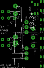
Since the solder pads for the SE and balanced version are arranged differently, I ordered a separate board for each version.
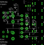
balanced Version:
Of course, two Muses boards are required here. On the MC-board the corresponding sockets are doubled.
The jumpers and diodes for the SE inputs must be populated. More detailed information can be found on my IronPre website.
Here I will document the setup in detail.
The MC-board now contains the possibility to use the Meanwell power supplies IRM02.
There is a 7pin connector to the IP-board which controls the relays. The power supply for the relays does not have to be assembled then. For this purpose there is a power supply on the MC-board. The diodes there are also omitted.
A 5-pin connector establishes the connection to the Muses chip. The board with the Muses chip now contains lateral contacts. This allows the board to be placed vertically on the IP board and soldered. Alternatively, there are holes at the height of the potentiometer solder pads, so that the connection can also be made with a wire.
The power supply for the Muse is provided by the IP power supply unit. There is a 3-pin plug connection for this purpose. From the positive voltage a 5V voltage for the digital isolator is generated on the Muses board. Therefore a 5-pin (gnd, +5V, SPI) connection. Thus the power supplies of the analog and the digital part are completely separated.
Since the solder pads for the SE and balanced version are arranged differently, I ordered a separate board for each version.
balanced Version:
Of course, two Muses boards are required here. On the MC-board the corresponding sockets are doubled.
The jumpers and diodes for the SE inputs must be populated. More detailed information can be found on my IronPre website.
Here I will document the setup in detail.
When you say, “The diodes there are also omitted” are you referring to diodes on the MC board or the diodes associated with the relays? I assume this still supports a mixed BAL/SE implementation.
MC-board probably refers to the microcontroller board. If I'm correct about that, it won't be the relay diodes.
The Se/bal control, which are controlled by the set jumpers and the necessary diodes are unaffected.
I have not made any concrete statements about this yet, because I would like to build the circuit first. But if I think this through correctly, these diodes need to be installed with the polarity reversed (opposite). With this, the control should then work as intended.
I have not made any concrete statements about this yet, because I would like to build the circuit first. But if I think this through correctly, these diodes need to be installed with the polarity reversed (opposite). With this, the control should then work as intended.
- Home
- Amplifiers
- Pass Labs
- Logic Solutions for Iron Pre Kits