The second last column is the spot noise figure you get when you connect an ordinary 47 kohm load to a V15 III cartridge, with no other noise sources at all. When you have a 3 dB noise figure target, you definitely need an electrically "cold" termination. It's worse for less lossy cartridges.
@rayfutrell: My noise criterion is also noise figure. But most RIAA stages do not achieve your criterion.

Hi Drone,Artificial intelligence will help us
A picture from the past, from a more developed civilization—when marketing was less developed. 😊
Links
Unfortunately, Artificial Intelligence seems to be rather incorrect.
Contrary to what it suggest, none of these listed Carts seem to have tapered Cantilevers.
1. Boron Tapered Cantilevers
- Lyra Atlas (SL, Lambda) – Uses a tapered boron tube for ultra-low mass and rigidity.
- Ortofon MC Anna Diamond – Features a tapered boron cantilever with diamond-coated stylus for extreme detail.
- Dynavector XV-1t – Tapered boron design for improved tracking and high-frequency response.
2. Sapphire Tapered Cantilevers
- Koetsu Urushi Vermilion/Platinum – Handcrafted with a tapered sapphire cantilever for lush midrange and durability.
- Clearaudio Goldfinger Statement – Uses a hollow tapered sapphire tube for minimal resonance.
3. Diamond-Coated or Solid Diamond Cantilevers
- ZYX Ultimate Airy – Tapered diamond-coated boron for near-zero distortion.
- Phasemation PP-2000 – Solid diamond tapered cantilever (rare and ultra-high-end).
Hans
In RF there's only one frequency to worry about though (I assume narrowband), but here its wideband and the noise has a whole spectrum, and parts of the spectrum are more annoying than others. 30% is nearly 3dB, the human perception of relative level is more like 0.25dB, though absolute level is probably more than twice that.
It more concrete terms reducing high-frequency hiss compared to mid-band "rushing" by as little as 1dB can be noticeably beneficial.
It more concrete terms reducing high-frequency hiss compared to mid-band "rushing" by as little as 1dB can be noticeably beneficial.
At the higher audio frequencies, the noise figure due to the 47 kohm load resistor is about 4 dB using a Shure V15 III (and higher using a less lossy cartridge), see post #101. It's all without any record playing, of course, but apparently record surface noise is mostly low-frequency noise.
In any case, it all says nothing without the mechanical response.
The mechanical response must have a huge peak for the Shure V15 III, as its electrical response is around -12 dB at 20 kHz while the overall response is still within about 1 dB there.
I made a silly error, I forgot to take the opposite of the phase of the impedance when calculating the admittance. With that corrected, the electrical response drops off only 8.2 dB rather than 12 dB at 20 kHz compared to 1 kHz. Anyway, you still need a big peak elsewhere to get a reasonably flat overall response.
Magnitude of the transfer from the Thévenin voltage (open-circuit voltage) to the loaded voltage with the recommended 47 kΩ in parallel with 450 pF load, normalized to the value at 1 kHz, vertical scale in dB, horizontal in Hz:
I would like to present the almost finished build of my RIAA preamp.
The design is courtesy of @MarcelvdG see: Single stage RIAA with 2nd order HPF Highly recommended.
For the load capacitance I decided on around 170 pF (all cabling included) following this recommendation: Ortofon 2M Red test
Especially on power down, there were 2 distinct plops, so I inserted a mute circuit on the output shorting to ground. You can see it in the top-middle of the record player.
Schematic:

Bode plot frequency response:

Noise and distortion:

Note: This was done before the amplifier was 'tinned in' and you can see some 50 Hz hum (and a spike at 150 Hz, which might be a measurement artifact since I see nothing at 100 Hz, so this doesn't seem a product of 50 Hz + 100 Hz). SNR appears to be around 80 dB (-100 dB down compared to -20 dB) with the THD around or in the noise-floor. After putting the RIAA amp in a shielded box, with the volume of my power-amp turned all the way up, and at around 50 cm listening distance, the whole set-up was completely silent. With my ears close up to the loudspeaker, hum was not present, noise is low, sometimes you can hear what I think is some shot noise? (random phenomenon).
Almost finished in my Pioneer PL-200:


The design is courtesy of @MarcelvdG see: Single stage RIAA with 2nd order HPF Highly recommended.
For the load capacitance I decided on around 170 pF (all cabling included) following this recommendation: Ortofon 2M Red test
Especially on power down, there were 2 distinct plops, so I inserted a mute circuit on the output shorting to ground. You can see it in the top-middle of the record player.
Schematic:
Bode plot frequency response:
Noise and distortion:
Note: This was done before the amplifier was 'tinned in' and you can see some 50 Hz hum (and a spike at 150 Hz, which might be a measurement artifact since I see nothing at 100 Hz, so this doesn't seem a product of 50 Hz + 100 Hz). SNR appears to be around 80 dB (-100 dB down compared to -20 dB) with the THD around or in the noise-floor. After putting the RIAA amp in a shielded box, with the volume of my power-amp turned all the way up, and at around 50 cm listening distance, the whole set-up was completely silent. With my ears close up to the loudspeaker, hum was not present, noise is low, sometimes you can hear what I think is some shot noise? (random phenomenon).
Almost finished in my Pioneer PL-200:
So, I got a little excited. Upon closer examination, with the volume pot set up to the 2 o'clock position, the set-up is silent. 2 o'clock on my amp is LOUD. 😛After putting the RIAA amp in a shielded box, with the volume of my power-amp turned all the way up, and at around 50 cm listening distance, the whole set-up was completely silent.
And the inspiration for the muting circuit came from this Youtube video. I just left out the parts for the speaker protection circuit (Q2, Q3 and associated parts). Works well.
Last edited:
How did you produce the Noise and Distortion image.
It seems you used a constant level input signal and applied a post Anti Riaa correction at the preamps output.
A Riaa preamp usually shows the Riaa correction curve in the noise spectrum but not in your case.
Hans
It seems you used a constant level input signal and applied a post Anti Riaa correction at the preamps output.
A Riaa preamp usually shows the Riaa correction curve in the noise spectrum but not in your case.
Hans
So you inserted a real cart or a comparable inductor plus resistor between anti riaa generator and preamp, true ?
Hans
Hans
No, soundcard generator out -> anti RIAA circuit -> RIAA preamp -> soundcard in -> PC running REW. This is not a lab set-up. Just something to humor myself.
Moving-magnet noise measurements without the cartridge inductance can give misleading results. Is the set-up also silent with a real cartridge?
I'd say that with the cartridge inserted, the noise level is either the same, or lower, than without. It makes it a little hard to determine, since the is considerable hum without the cartridge inserted and you need to try and hear through the hum to judge the noise.Is the set-up also silent with a real cartridge?
Overall, I can tell there is a difference with the 170 pF loading vs. the orginal 370 pF loading which my integrated amp has. The highs are less, as expected.
Can or will? I had not heard of this. And does that depend on the cartridge, the preamp, or both? Doesn't that make it very hard to compare preamp results if the outcome depends on the cartridge?Moving-magnet noise measurements without the cartridge inductance can give misleading results.
Overall, I am very satisfied with this little preamp. It meets the requirements that I had set:
- Lower gain
- Adjustable loading capacitance (lower than my integrated amp)
Noise always depends on the cartridge. If you're chasing minimum noise you must always design the amplifier with its source in mind, and that means you need to know exactly what the source impedance is as a function of frequency. And yes, that does make it harder to compare pre-amplifier designs. Achieving low noise requires considerable care and attention to detail. And, as Marcel will point out, a moving magnet cartridge requires a synthesised load resistance. There shouldn't be any hum; twisted pair in screen from the arm base to RIAA stage usually fixes that problem.
It will, see for example https://www.audiosciencereview.com/...and-sinad-of-mm-phono-preamps-properly.60594/Can or will? I had not heard of this
In practice the cartridge data doesn't vary so much that it would a have significant impact on noise measurements... but replacing the cart with short or very low source impedance gives grossly incorrect results.
Since the noise spectrum in your recording did not make sense to me, I simulated the circuit,I would like to present the almost finished build of my RIAA preamp.
The design is courtesy of @MarcelvdG see: Single stage RIAA with 2nd order HPF Highly recommended.
For the load capacitance I decided on around 170 pF (all cabling included) following this recommendation: Ortofon 2M Red test
Especially on power down, there were 2 distinct plops, so I inserted a mute circuit on the output shorting to ground. You can see it in the top-middle of the record player.
Schematic:
View attachment 1460792
Bode plot frequency response:
Noise and distortion:
View attachment 1460795
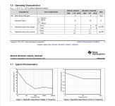
Small problem is that the TI noise specifications of the 5532A are very inconsistent between specs and graphs, see first attachment.
Specs tells a current noise of 0.7pA/rtHz@1Khz and 2,7pA/rtHz@30Hz, but the graph shows resp 1pA/rtHz and 1.2pA/rtHz, very strange.
I stayed on the low side with my sims.
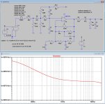
Now simulating the circuit directly from a A-Riaa source, see second attachment, results as expected in a noise pattern at the output that exactly reflects the Riaa curve.
Since your image shows a noise pattern that's going upwards instead of downwards as from 100Hz to 20Khz, your measurement gear must have an additional source of noise, polluting the recording.
When inserting a virtual Cart in the form of 500mH + 600R, the noise spectrum above 1Khz starts to raise, see third attachment.
The simulated S/N with the used 5532A noise numbers results in 66 dBA including the used Cart, not exceptional but good enough.
Hans
Attachments

Last edited:
Thanks EC8010, KSTR and Hans Polak for your feedback!
The circuit I used to produce the Bode plot and THD+N measurements is below. This is both different from a low impedance source and a low impedance A-RIAA source. This was inserted between the signal generator and pre-amp. For the Bode plot, both pre-amp output and signal generator output ('UIT' on the schematic) were first calibrated (with the 5K pot) to 0 dB @ 1 kHz, and then for the measurement compared, to get rid of potential inaccuracies of the generator, so you are only left with deviations from the A-RIAA and RIAA pre-amp circuit.
I will have to study your contributions and see if I can produce a more meaningful test result.
- Home
- Source & Line
- Analogue Source
- Load capacitance on MM cartridge