Reply to post #119:
Those typical characteristics make no sense at all. For one thing, the 1/f-noise corner frequency is normally higher for the noise current than for the noise voltage of a bipolar transistor.
Judging by the input bias current and the fact that there is no base current compensation, I would expect the input noise current density of the NE5532 to drop to √(2q • 200 nA) ~= 0.2532 pA/√Hz at high frequencies. I never measured if it really does, though.

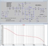
I would be more worried about your voltage divider to bias the input at 7.5Volt.
As you can see, PSRR is quite miserable probably the reason for your unexpected noise spectrum.
You better use a high grade voltage regulator like the LT1763 or one from the LT3045 serie.
Hans
As you can see, PSRR is quite miserable probably the reason for your unexpected noise spectrum.
You better use a high grade voltage regulator like the LT1763 or one from the LT3045 serie.
Hans
Attachments
I agree, IMHO better use not unipolar but bipolar power supply, as in https://www.diyaudio.com/community/threads/my-opa1656-riaa-preamp-one-more.425815/post-8000058 This eliminates the need for power supply filtering - the operational amplifier's 120...140 dB PSRR is much better than any integrated regulator in the case of a single-polar supply. In addition, there is no need for a bunch of separating electrolytes (with too long charging time at power on state).I would be more worried about your voltage divider to bias the input at 7.5Volt.
Last edited:
I'd say that with the cartridge inserted, the noise level is either the same, or lower, than without. It makes it a little hard to determine, since the is considerable hum without the cartridge inserted and you need to try and hear through the hum to judge the noise.
Are you comparing cartridge versus reverse RIAA circuit or cartridge versus open input?
Can or will? I had not heard of this. And does that depend on the cartridge, the preamp, or both? Doesn't that make it very hard to compare preamp results if the outcome depends on the cartridge?
The point is that a preamplifier has both equivalent input noise voltage and equivalent input noise current. The effect of the current increases with source impedance. When you measure without the cartridge inductance, the source impedance is too low and you underestimate the effect of the equivalent input noise current.
In a typical moving-magnet phono preamplifier with a valve or a FET as input device, it's the thermal noise of the 47 kohm input parallel resistor that dominates the equivalent input noise current. The resistor produces about 0.5869 pA/√Hz of thermal noise current at 20 degrees Celsius. Hence, when you want to compare phono preamplifiers in this category and use a too low source impedance, the one with the lowest noise voltage will perform best, and as they all have the same noise current, that is also the best with a real cartridge. That is, the measurements are inaccurate, but the ranking is still correct.
It gets worse when some of the preamplifiers have a bipolar input stage. The shot noise of the base current then adds to the equivalent input noise current. With a bipolar op-amp with base current compensation, the base current compensation also adds to the equivalent input noise current, sometimes quite dramatically. When you then measure with a too low source impedance, it could very well be that the amplifier that performs worst with the cartridge as source gives the best result in the measurement.
(Since 1939, techniques have been known to reduce the equivalent input noise current below 0.5869 pA/√Hz while still having a 47 kohm input resistance and without needing to cool the input resistor with liquid nitrogen or helium. The inventor called it an electrically "cold" resistance, but there are other terms in use for the exact same thing. It is not often used for phono preamplifiers, but it is used all over the place in all sorts of radio receivers.)
Overall, I am very satisfied with this little preamp. It meets the requirements that I had set:
- Lower gain
- Adjustable loading capacitance (lower than my integrated amp)
That's nice to read!
Last edited:
I know that, but my turntable has an unipolar supply only, and I wanted to see how far I could get by utilizing that and not going the route of converting unipolar supply to bipolar supply, for instance with a charge pump. I ran the pre-amp externally with a bipolar supply as well (after making the neccesairy changes to the pre-amp) and the difference was not such that I felt I needed to use a bipolar supply. I must admit at the time of that test the pre-amp wasn't shielded, so I might have been listening to hum pick-up rather than supply induced hum. I need to say though that neither noise nor hum is audible at normal listening distances in my current unipolar supply, shielded, pre-amp set-up.IMHO better use not unipolar but bipolar power supply,
I tried comparing noise with the cartridge inserted versus open input (with the cartridge removed from the tone arm)Are you comparing cartridge versus reverse RIAA circuit or cartridge versus open input?
Thanks for the explanation. I have also read the post on audiosciencereview linked in a previous post.In a typical moving-magnet phono preamplifier with a valve or a FET as input device, it's the thermal noise of the 47 kohm input parallel resistor that dominates the equivalent input noise current.
That same article tested the NE5534 in an MM set-up, and it faired quite well. I am using the NE5532, which I think is slightly worse, but the NE5534 came in a close second after a JFET input Opamp and was a better performer than the OPA134. I also read that D. Self wrote that the NE5532/34 is a sensible choice for an MM pre-amp.It gets worse when some of the preamplifiers have a bipolar input stage.
I might experiment further with the power supply. The two options I see are bipolar regulated (via a charge pump) or perhaps I will go the battery route. I have measured the current consumption at 7 mA idle. Allowing 2-3 mA for the drive signal, and I can expect 10 mA current draw, which I think is fine for a battery supply.
I would be more worried about your voltage divider to bias the input at 7.5Volt.
As you can see, PSRR is quite miserable probably the reason for your unexpected noise spectrum.
You better use a high grade voltage regulator like the LT1763 or one from the LT3045 serie.
Hans
The amplifier is dead quiet according to Arjen, so I wouldn't worry about it at all. As you can see in your own plot or by inspecting the circuit, power supply rejection gets better with frequency, so power supply noise can at most affect the noise at very low frequencies somewhat.
What you simulated is the transfer from the supply to the output (while what is usually called the PSRR is referred to the input). At audio frequencies up to 50 Hz, the gain from input to output is roughly 300 times, so the 5 nV/√Hz voltage noise of the NE5532 results in 1.5 μV/√Hz at the output. The gain you simulated from the supply to the output drops from -7 dB to -24 dB from 20 Hz to 50 Hz.
The supply is supposed to be regulated. Assuming a really poor regulator with 1 μV/√Hz of output noise, the noise contribution of the supply at the output is more than 10 dB below the effect of the voltage noise of the NE5532 at 20 Hz, and more than 20 dB at 50 Hz.
At all frequencies between 150 Hz and 20 kHz, the simulated gain from supply to output is below -50 dB and the gain from input to output is above 10 dB. That means that 1 μV/√Hz at the supply corresponds to less than 1 nV/√Hz equivalent at the input.
Regarding hum, suppose the unregulated supply has 1 V RMS of ripple at either 50 Hz or 100 Hz and the poor regulator has 60 dB of ripple rejection. That boils down to 1 mV RMS at the regulated supply. With the simulated gain of -24 dB at 50 Hz, -40 dB at 100 Hz from supply to output, the resulting ripple at the output would be either -84 dBV at 50 Hz or -100 dBV at 100 Hz. With a nominal level of about 160 mV (30 dB above 5 mV), so -16 dBV, the signal-to-hum ratio would be 68 dB (50 Hz) or 84 dB (100 Hz). The latter case seems more likely, as single-phase rectification is not often used. If needed, the suppression could always be improved by using two RC sections instead of the 4.7 kΩ - 47 μF that is now used. No need to use expensive and almost impossible to hand solder regulators, as far as I can see.
That same article tested the NE5534 in an MM set-up, and it faired quite well. I am using the NE5532, which I think is slightly worse, but the NE5534 came in a close second after a JFET input Opamp and was a better performer than the OPA134. I also read that D. Self wrote that the NE5532/34 is a sensible choice for an MM pre-amp.
Definitely. When I wrote: "It gets worse when some of the preamplifiers have a bipolar input stage", I didn't mean that phono preamplifiers with a bipolar input stage necessarily perform worse than those with FET inputs, but that the correlation between measurements with a low source impedance and with a realistic source impedance gets worse because you cannot assume the noise current to be the same for all amplifiers anymore. For example, a phono preamplifier with an LT1028 would outperform one with an NE5534A for very low source impedances, while one with an NE5534A would outperform one with an LT1028 at normal moving-magnet cartridge impedances.
Marcel,The amplifier is dead quiet according to Arjen, so I wouldn't worry about it at all. As you can see in your own plot or by inspecting the circuit, power supply rejection gets better with frequency, so power supply noise can at most affect the noise at very low frequencies somewhat.
What you simulated is the transfer from the supply to the output (while what is usually called the PSRR is referred to the input). At audio frequencies up to 50 Hz, the gain from input to output is roughly 300 times, so the 5 nV/√Hz voltage noise of the NE5532 results in 1.5 μV/√Hz at the output. The gain you simulated from the supply to the output drops from -7 dB to -24 dB from 20 Hz to 50 Hz.
The supply is supposed to be regulated. Assuming a really poor regulator with 1 μV/√Hz of output noise, the noise contribution of the supply at the output is more than 10 dB below the effect of the voltage noise of the NE5532 at 20 Hz, and more than 20 dB at 50 Hz.
At all frequencies between 150 Hz and 20 kHz, the simulated gain from supply to output is below -50 dB and the gain from input to output is above 10 dB. That means that 1 μV/√Hz at the supply corresponds to less than 1 nV/√Hz equivalent at the input.
Regarding hum, suppose the unregulated supply has 1 V RMS of ripple at either 50 Hz or 100 Hz and the poor regulator has 60 dB of ripple rejection. That boils down to 1 mV RMS at the regulated supply. With the simulated gain of -24 dB at 50 Hz, -40 dB at 100 Hz from supply to output, the resulting ripple at the output would be either -84 dBV at 50 Hz or -100 dBV at 100 Hz. With a nominal level of about 160 mV (30 dB above 5 mV), so -16 dBV, the signal-to-hum ratio would be 68 dB (50 Hz) or 84 dB (100 Hz). The latter case seems more likely, as single-phase rectification is not often used. If needed, the suppression could always be improved by using two RC sections instead of the 4.7 kΩ - 47 μF that is now used. No need to use expensive and almost impossible to hand solder regulators, as far as I can see.
That’s all true when the 15V voltage comes from a regulated supply, but I’ve not seen any mentioning of that.
The reason I suspected the supply was because of the unexpected noise spectrum not showing a Riaa shape.
When Arjen would do the same test with 18Volt from two 9Volt batteries, we could see what impact the used 15V supply had.
You also mentioned “dead silent” but what I read from Arjen was that this was difficult to tell because of the mains hum.
Hans
The fact that the supply is regulated is mentioned in another thread, post #144 of https://www.diyaudio.com/community/...rworth-high-pass-included.413649/post-7972685 It's 16.5 V there, no idea why it dropped 1.5 V later.
@arjen6t8
I made a calculation error in the 66dBA S/N ref 5mV@5cm/sec that I mentioned yesterday.
It should be 76dBA and that's absolutely excellent.
Hans
I made a calculation error in the 66dBA S/N ref 5mV@5cm/sec that I mentioned yesterday.
It should be 76dBA and that's absolutely excellent.
Hans
This is a big mistake. The input really is never left open.I tried comparing noise with the cartridge inserted versus open input (with the cartridge removed from the tone arm)

You also mentioned “dead silent” but what I read from Arjen was that this was difficult to tell because of the mains hum.
He only had noticable hum with the input open, if I understood it correctly. An open MM phono input is very sensitive to capacitively coupled hum and the filtering of supply ripple in the single-supply circuit is less effective with open input than with a connected cartridge (as there is no voltage division between the 100 kohm resistor and the cartridge impedance in series with 1.5 uF when there is no cartridge).
Congratulations on a really great preamp design and build and a beautiful integration with the turntable.
I think you might enjoy using the Ortofon test record to fine tune the load capacitance and resistance for your specific build on each channel individually. I spent the $50 and found it worked well. I played the record and did captures and did the analysis using the free Audacity software. I wasn't so smart and soldered my load resistor and capacitors in and haven't gone back to make adjustments.
I also found it to be informative to compare the measured noise spectrum plot of the system running with the tone arm up off the record with the spectrum of the quietest blank track on a new record I could find. I suspect your new system has a noise floor that is 15 to 20 dB lower than any record. So that is wonderful.
Hi Hans, let me get back tomorrow on your question, then I will have time to post the power supply schematic and some clarification on my 'dead silent' statement vs. measured and audible noise/hum. My calculations show I have around 65 dB @ 100 Hz rejection from RCRC filtering in my supply. I will also measure the PS input ripple. If this stays under 1 V RMS, then I should be good (according to Marcel's calculation).
Thx for replying.Hi Hans, let me get back tomorrow
Do you happen to have two 9 Volt batteries to get a noiseless 18 Volt supply.
That would give you a nice reference.
Hans
Below is the supply as originally found in the turntable and the final supply. I modified the zener with a double RCRC filter. First corner frequency is 1/(2*PI*470*100u) = 3,39 Hz. This is around 5 oct. below 100 Hz. Second corner frequency is 1.54 Hz. This is around 6 oct. below 100 Hz. So I'm getting around 5,5 * 12 dB = 66 dB attennuation at 100 Hz from the RCRC filtering sans the zener. The ripple voltage is 572 mV, so according to MarcelvdG, the RCRC filtering alone gives enough rejection. The capacitor in the RIAA amp was enlarged to 220 uF when I built the amp back from dual to single supply.

Ripple voltage under load

Original power supply

Final power supply: "A" supplies the RIAA amp, "B" is for the muting circuit. C2 was replaced with 470 uF. A UF4007 was inserted to minimise rectifier switching noise. Voltages indicated are measured voltages.

Pre-amp schematic
Some comments on my 'dead silent' statement. Perhaps I should have written 'silent' instead. I can hear noise & hum when I turn up the volume setting to 'very loud' sitting at around 0,5 m from the speakers. At normal listening loudness and listening distances, no pre-amp noise or hum is heard (this is with the cart lifted). When the cart is in the record at a silent piece, any pre-amp noise/hum is drowned in the record surface noise.
I have tried making new measurements. I shall refrain from testing the pre-amp with a signal generator - as this requires a coil (and resistance) in series with the generator as I've learned - since I don't have a coil in the required inductance range. Instead, I have measured the output of the pre-amp with the cart inserted into the tone-arm, using a digital USB scope (Pico 2000). First graph is the scope with shorted input Averaged, second is output of pre-amp Averaged, third is a (technically good) record playing using the Peak Hold function.

1. Noise floor of PICO scope with shorted inputs, averaged. Noise floor = -116 dBV

2. Noise floor pre-amp out, cart inserted, averaged. 50 Hz hum @ -81 dBV. Spikes up to -81 dBV. Otherwise noise floor @ -106 dBV.

3. Record playing using Peak Hold function of scope. Max levels - 15 dBV
I have the following question:
Does it make sense that I see a noise floor at around -106 dBV in graph 2 when the expected SNR should be around 76 dBA?
When I look at graph 3, the measurement seems OK, as the cart is specified for 5,5 mV @ 1 kHz, the pre-amp gain is 34 = 187 mV and -15 dBV = 138 mV.
PS - I left the USB soundcard / REW route for now and went back to my trusted Pico scope.
I will try running the pre-amp later on 2 x 9V batteries to see if the junk from 5 - 15 kHz is coming from the turntable and see if this does anything to the 50 Hz hum.
PPS - I wanted to add the .pdf of the complete turntable schematics, but I can't figure out where to upload those.
Ripple voltage under load
Original power supply
Final power supply: "A" supplies the RIAA amp, "B" is for the muting circuit. C2 was replaced with 470 uF. A UF4007 was inserted to minimise rectifier switching noise. Voltages indicated are measured voltages.
Pre-amp schematic
Some comments on my 'dead silent' statement. Perhaps I should have written 'silent' instead. I can hear noise & hum when I turn up the volume setting to 'very loud' sitting at around 0,5 m from the speakers. At normal listening loudness and listening distances, no pre-amp noise or hum is heard (this is with the cart lifted). When the cart is in the record at a silent piece, any pre-amp noise/hum is drowned in the record surface noise.
I have tried making new measurements. I shall refrain from testing the pre-amp with a signal generator - as this requires a coil (and resistance) in series with the generator as I've learned - since I don't have a coil in the required inductance range. Instead, I have measured the output of the pre-amp with the cart inserted into the tone-arm, using a digital USB scope (Pico 2000). First graph is the scope with shorted input Averaged, second is output of pre-amp Averaged, third is a (technically good) record playing using the Peak Hold function.
1. Noise floor of PICO scope with shorted inputs, averaged. Noise floor = -116 dBV
2. Noise floor pre-amp out, cart inserted, averaged. 50 Hz hum @ -81 dBV. Spikes up to -81 dBV. Otherwise noise floor @ -106 dBV.
3. Record playing using Peak Hold function of scope. Max levels - 15 dBV
I have the following question:
Does it make sense that I see a noise floor at around -106 dBV in graph 2 when the expected SNR should be around 76 dBA?
When I look at graph 3, the measurement seems OK, as the cart is specified for 5,5 mV @ 1 kHz, the pre-amp gain is 34 = 187 mV and -15 dBV = 138 mV.
PS - I left the USB soundcard / REW route for now and went back to my trusted Pico scope.
I will try running the pre-amp later on 2 x 9V batteries to see if the junk from 5 - 15 kHz is coming from the turntable and see if this does anything to the 50 Hz hum.
PPS - I wanted to add the .pdf of the complete turntable schematics, but I can't figure out where to upload those.
Last edited:
Your Picoscope presumably measures the noise in one DFT bin, or maybe 1.5 DFT bins or so due to windowing. That's a much narrower bsndwidth than is used for A-weighted integrated noise measurements. The smaller the bandwidth, the lower the noise in that bandwidth.
All good fun. Great to see such good work and documentation. My attempt at two cents. I'm no expert, so there may be an error in my results.
So -106 dBV noise floor relative to the - 15 dBV signal is 106 - 15 = 91 dB SNR ignoring the spikes. That's a big number.
It would be interesting to compare that number with the thermal noise of the 47 kOhm resistor that is the part limiting the noise floor if you had a perfect noise free preamp. I created a spice simulation that models a typical cartridge and the specified resistor and capacitor loading and computed the noise. Relative to the cartridge output from 20 Hz to 20 kHz I estimated the noise to be about 63 dB below the 5 cm/s standard signal level from a record.

total_output_refered_rms_noise: INTEG(v(onoise))=2.53583e-06 FROM 10 TO 20000
Assuming the cartridge output of 3.5 mV for 5 cm/s stylus motion at 1 kHz for moving magnet cartridge
20*log10(3.5e-3/2.535e-6) = 62.9 dB SNR of a phono cartridge with cap and resistor loading
circuit shown in the schematic above.
This result doesn't include the high frequency roll off of the RIAA playback equalization, but as that is applied to both the signal and the noise it should not change the SNR but it will change the absolute noise value.
Of course when you have a needle tracking a silent groove on a record the noise is much higher.
When I made measurements of the differential input preamp I designed and built last year I also saw a noise floor that was far below what I had calculated for the circuit performance using the noise modeling in LTSpice. I expected to achieve. It turned out that my turntable had a relay that shorted the cartridge output when the record was not playing. I had to fool around to defeat that before I could get a measurement.
It will be interesting to see if the source of the noise spikes can be found.
So -106 dBV noise floor relative to the - 15 dBV signal is 106 - 15 = 91 dB SNR ignoring the spikes. That's a big number.
It would be interesting to compare that number with the thermal noise of the 47 kOhm resistor that is the part limiting the noise floor if you had a perfect noise free preamp. I created a spice simulation that models a typical cartridge and the specified resistor and capacitor loading and computed the noise. Relative to the cartridge output from 20 Hz to 20 kHz I estimated the noise to be about 63 dB below the 5 cm/s standard signal level from a record.
total_output_refered_rms_noise: INTEG(v(onoise))=2.53583e-06 FROM 10 TO 20000
Assuming the cartridge output of 3.5 mV for 5 cm/s stylus motion at 1 kHz for moving magnet cartridge
20*log10(3.5e-3/2.535e-6) = 62.9 dB SNR of a phono cartridge with cap and resistor loading
circuit shown in the schematic above.
This result doesn't include the high frequency roll off of the RIAA playback equalization, but as that is applied to both the signal and the noise it should not change the SNR but it will change the absolute noise value.
Of course when you have a needle tracking a silent groove on a record the noise is much higher.
When I made measurements of the differential input preamp I designed and built last year I also saw a noise floor that was far below what I had calculated for the circuit performance using the noise modeling in LTSpice. I expected to achieve. It turned out that my turntable had a relay that shorted the cartridge output when the record was not playing. I had to fool around to defeat that before I could get a measurement.
It will be interesting to see if the source of the noise spikes can be found.
This result doesn't include the high frequency roll off of the RIAA playback equalization, but as that is applied to both the signal and the noise it should not change the SNR but it will change the absolute noise value.
That's only true when your signal has a similar spectral distribution as the noise. It's certainly not true when the signal is a 1 kHz sine wave.
- Home
- Source & Line
- Analogue Source
- Load capacitance on MM cartridge