LME49810/LME49830
After successfully completing a GainClone amp I got inspired by this thread, specially the posts from Panson Poon, to design and build replacement power amps for my burned out Marantz SR-6000DC. Since the STK-0080's of the Marantz also set my speakers on fire, I decided to include a DC-servo descending from P-A Sjöströms GainClone and a speaker protection circuitry of my own origin. The first version is uses BJT/LME49810, but the PCB is designed to be used with MOSFET's and LME49830 as well.
My measuring equipment is limited to a scope an a couple of DVM's so I can't give any objective data. The power is there and it sound alright ti me at least.
I eagerly wait for Panson Poom to finish his project, meanwhile I kep on messing about on my own. I would appreciate any comments to the attached schematics, there is most certainly room for improvements!
Attachments
Hi: I don't see schematics either for your amp or the speaker protection circuit on my browser. Please check your attachments.
Segran: You are going to use a Darlington on the output (TIP142/TIP147) -- the LME49810 and LM4702 have to do a lot of huffing and puffing to drive the TIP35/36C.
While you're at it, consider using one of National's newer audio opamps like the LM4562 dual rather than the LM833 -- LM833 is tried and true, but the LM4562 is in a different class entirely.
While you're at it, consider using one of National's newer audio opamps like the LM4562 dual rather than the LM833 -- LM833 is tried and true, but the LM4562 is in a different class entirely.
Re: LME49810/LME49830
Hi Segran,
As pointed by jackinnj, you need to add driver to your amplifier. The LME49180 internal driver/buffer has not enough driving capability. Your expected output is 100 W. The RMS current is 3.5 A for 8 Ohm. Since TIP35/36C typ. current gain is 40, you need 88 mA rms base current. The peak value is 125 mA which is two times the chip's capability. Your amplifier may clip earlier or distortion increases substantially at high level.
I did some load test to LME49810 and posted the results in this thread.
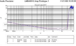
Below is the THD for my amp with and without driver. One pair of NJL3281/1302D were used. Their typ current gain is 75. You can see the THD is about doubled for no driver.
Thanks for your interest in my project. It is basically finished. Two channels have been built. A test report will be ready soon.
Segran said:... I would appreciate any comments to the attached schematics, there is most certainly room for improvements!
Hi Segran,
As pointed by jackinnj, you need to add driver to your amplifier. The LME49180 internal driver/buffer has not enough driving capability. Your expected output is 100 W. The RMS current is 3.5 A for 8 Ohm. Since TIP35/36C typ. current gain is 40, you need 88 mA rms base current. The peak value is 125 mA which is two times the chip's capability. Your amplifier may clip earlier or distortion increases substantially at high level.
I did some load test to LME49810 and posted the results in this thread.
Below is the THD for my amp with and without driver. One pair of NJL3281/1302D were used. Their typ current gain is 75. You can see the THD is about doubled for no driver.
Thanks for your interest in my project. It is basically finished. Two channels have been built. A test report will be ready soon.
Attachments
If one is asking an amplifier to drive a real speaker then the peak transient current can be very much higher than what a resistive load will draw.
The suggestion for worst case impedance/reactance (but not including electrostatics) is Ipk<=Vpk / RLoad / 0.35.
for 100W into 8ohm this gives a worst case peak current of ~14Apk.
change the load to 4ohm (200W into 4r0) and this transient peak can rise to 28Apk.
The chip needs a driver and an output device and the output devices will probably need to be doubled for that 14Apk to avoid the gain droop inherent in all BJTs.
For the 4ohm loading the outputs will need to be at least tripled.
Hello
I'm new there . Sorry for my bad english ant sometimes stupid questions .
I would like to make lme49810 by paokakis scheme http://www.diyaudio.com/forums/attachment.php?s=&postid=1333284&stamp=1193215339 but i didn't know how to make pcb.
Can anybody help my with pcb?
I'm new there . Sorry for my bad english ant sometimes stupid questions .
I would like to make lme49810 by paokakis scheme http://www.diyaudio.com/forums/attachment.php?s=&postid=1333284&stamp=1193215339 but i didn't know how to make pcb.
Can anybody help my with pcb?
zilvinasn. said:... i didn't know how to make pcb.
Can anybody help my with pcb?
Hi zilvinasn,
Is it you First project ever? Will you consider start with a ready made PCB like http://www.diyaudio.com/forums/showthread.php?postid=1235697#post1235697? This is worth for your first project. You need to learn not only making PCB, but also construction (soldering, wiring).
On the other hand, you can build it on a prototyping board like I did before http://www.diyaudio.com/forums/attachment.php?s=&postid=1275910&stamp=1186815503 .
There are many online resources for homemade PCB techniques. Google search ....
LME49810/49830 100W project
Thanks for all the valuable comments, they are most appreciated! I will immidiately order TIP 142/147. The TIP35/36 I got have current gain of 140-180 so the chip manages to drive the output stage - barely... I considered including a driver stage, but I think that Darlingtons will do the trick for this first version. The components I choose was more or less what I had lying around, hence the LM833.
Would I need a driver stage for the IRFP240/9240 MOSFET version as well? The Application notes I have read suggests that it is not needed, provided the output stage has sufficient current gain.
Sorry for the missing schematics of the speaker protection, hope it works this time
Attachments
Re: LME49810/49830 100W project
The protection schematic is still missing.
Driver is suggested for more than one pair of MOSFETs.
Segran said:Would I need a driver stage for the IRFP240/9240 MOSFET version as well? The Application notes I have read suggests that it is not needed, provided the output stage has sufficient current gain.
Sorry for the missing schematics of the speaker protection, hope it works this time
The protection schematic is still missing.
Driver is suggested for more than one pair of MOSFETs.
Hi,
the window comparator is waiting for signals with a peak voltage above the ref level of D14 & D15.
Much of you music will have transients above this level nearly continuously.
I would prefer to see the two filters before the comparator.
Add a load to the other relay terminal. Maybe try 47R 5W to take the amplifier output to ground. Otherwise the arc across the relay may never extinguish when the output stage sends DC. Hopefully the power resistor will survive until the rail fuse blows.
panson_hk said:
Hi zilvinasn,
Is it you First project ever? Will you consider start with a ready made PCB like http://www.diyaudio.com/forums/showthread.php?postid=1235697#post1235697? This is worth for your first project. You need to learn not only making PCB, but also construction (soldering, wiring).
On the other hand, you can build it on a prototyping board like I did before http://www.diyaudio.com/forums/attachment.php?s=&postid=1275910&stamp=1186815503 .
There are many online resources for homemade PCB techniques. Google search ....
gmikol's layout looks good to me. Has anyone designed a layout for a verticle heatsink setup, i.e all the IC's on one side?
LME49810
Hi everybody,
is there any possibility to use the backer clamp signal to make some protection ?
Any idea for a soft limiter ?
Thank you.
Franco
Hi everybody,
is there any possibility to use the backer clamp signal to make some protection ?
Any idea for a soft limiter ?
Thank you.
Franco
Thanks AndrewT for your suggestions. The reason for having the filters post the window comparator is to get a quick reaction when a DC level above 0.6V appears at theamp output. Adding filter before the comparators would seriously delay the reaction. Practival testing reveals that the circuit only reacts within 20 mS when there is DC, or at subsonic frequensys. Perhaps not the ideal design for a subwoofer, but the filter can be adapted to frequencies below the current 10-15 Hz. The resistor you suggested to kill the arc is yet another good idea. I am using a relay that is rated 10A @ 50VDC (16A @30VDC), unfortunately it is only SP. The DP version is only rated 6A@30VDC.
Heatsink for LME49810/49830
Hi, have anyone any suggestions for heatsink to be used with the LME498xx series? The Aavid suggested by National seems to be very hard to get.
Hi, have anyone any suggestions for heatsink to be used with the LME498xx series? The Aavid suggested by National seems to be very hard to get.
Re: Heatsink for LME49810/49830
I did not make any math. But my experience ...
I just use a RAM heat sink for my LME49810 amp with +/- 55 V. In 28C room temp, open frame, the chip+heat sink just gets warm during test.
Segran said:Hi, have anyone any suggestions for heatsink to be used with the LME498xx series? The Aavid suggested by National seems to be very hard to get.
I did not make any math. But my experience ...
I just use a RAM heat sink for my LME49810 amp with +/- 55 V. In 28C room temp, open frame, the chip+heat sink just gets warm during test.
Attachments

AndrewT said:If one is asking an amplifier to drive a real speaker then the peak transient current can be very much higher than what a resistive load will draw.
The suggestion for worst case impedance/reactance (but not including electrostatics) is Ipk<=Vpk / RLoad / 0.35.
Hi Andrew,
Is 0.35 a rule of thrumb? Do you know any load simulator (RLC network) for speaker used widely in the field? I found one from Ben Duncan's book.
Attachments

Hi,
yes, it's a near worst case estimate that is quoted by a very few authors on this Forum.
Most seem to agree that peak transient current into a crossover is worse than the Re value would indicate.
Many use a factor of 2 increase, a few use 2.5 times.
The 3 times appears to only happen on fast starting or fast stopping signal when the various reactances and VC back emf source or sink current.
Because this worst case can only happen as a transient it does little to stress the SOAR of the output stages due the tiny heating effect and the tolerance of SS to very fast signals.
Where it becomes crucial is when gain droop in the output devices causes the base current to rise and that in turn sources extra current from the drivers and then these too enter the gain droop region and source extra current from the VAS and, if fitted, the pre-driver.
It's precisely this peak current ability that chipamps cannot match and worse so as the load impedance drops.
The 49810 needs a high gain, wide low droop current range driver before the output device.
ESP and a few others publish speaker equivalent circuits. Try joining a pair through a real crossover and then simulate using sinewaves and compare to slow rising square waves. D. Self did a chapter on Output Stages where this simulation and worse is discussed in detail.
panson_hk said:
Hi zilvinasn,
Is it you First project ever? Will you consider start with a ready made PCB like http://www.diyaudio.com/forums/showthread.php?postid=1235697#post1235697? This is worth for your first project. You need to learn not only making PCB, but also construction (soldering, wiring).
On the other hand, you can build it on a prototyping board like I did before http://www.diyaudio.com/forums/attachment.php?s=&postid=1275910&stamp=1186815503 .
There are many online resources for homemade PCB techniques. Google search ....
Hello panson_hk,
It's not my first project. I have made amplifier with tda7294 and lm8560q and a few another. I also know how to make pcb but I didn't know how to make layouts (pcb picture with computer) .
Actualy I don't know how to use programs and how I should put elements on pcb. I mean i don't know about pcb design.
(I know how to soldering but i didn't know about wiring.)
That is my most important problem (pcb design).
I don't have these things which was in picture http://www.diyaudio.com/forums/attachment.php?s=&postid=1275910&stamp=1186815503
but i make somekind of that . And it is working so i want finish this project.
🙄
So which pcb i should use ? Or mabby someone can help my with making pcb for this http://www.diyaudio.com/forums/atta...tamp=1193215339 scheme.
- Home
- Amplifiers
- Chip Amps
- LME49810 - a new cousin for LM4702