Hi Panson,
40W into 8r0 is very low for a +-35Vdc PSU.
30W into 4r0 indicates there is something wrong.
40W into 8r0 is very low for a +-35Vdc PSU.
30W into 4r0 indicates there is something wrong.
AndrewT said:Hi Panson,
40W into 8r0 is very low for a +-35Vdc PSU.
30W into 4r0 indicates there is something wrong.
I am guessing the driver+output stage overload the chip. The source pin of the chip and output are measured and shown below. You can see the chip clips as well. I will change the driver to increase its current gain. Any advice?
Attachments
Hi Panson,
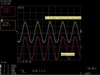
explain the readings on the scope traces.
It looks to me that the input is 3Vpp (=~1Vac) and that the output is 60Vpp (=~21Vac).
Please confirm the scope settings and readings and also measure the input and output voltages with voltmeter set to Volts AC.
What is the gain setting of the amplifier?
explain the readings on the scope traces.
It looks to me that the input is 3Vpp (=~1Vac) and that the output is 60Vpp (=~21Vac).
Please confirm the scope settings and readings and also measure the input and output voltages with voltmeter set to Volts AC.
What is the gain setting of the amplifier?
Hi Andrew,
You have good eyes!
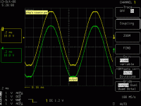
CH2 1V/scale was connected to a monitor output of AP. The level did not reflect the true value. I focued on the wave shape.
Let me show you a new scope capture where both channels connect to the circuit directly. It appears to me that the clip originates from the chip. It might be overloaded.
You have good eyes!
CH2 1V/scale was connected to a monitor output of AP. The level did not reflect the true value. I focued on the wave shape.
Let me show you a new scope capture where both channels connect to the circuit directly. It appears to me that the clip originates from the chip. It might be overloaded.
Attachments
And what is the circuit you use?
What I know is BD139/140 and NJL3281D/1302D.
Now if you have +35 Volt supply and put out 30 Volt peak
we then need to look for
- how much drop-out voltage chip need
- and add the drop across BD139 + 3281
These are data that can be found in datsheets. Normally.
And we should provide a bit of margin, as well. Not to endup withiin the combined drop-out region.
I do not think, in this case, it is the limited output drive current from chip sources, that will effect.
Because both BD139/140 and NJL3281D/1302D has good current gains = will not need too much AC-current drive.
+29dB=28.2times
But your input to output looks more like 20times.
Reduce the input slightly and measure your input output voltages and scope readings.
But your input to output looks more like 20times.
Reduce the input slightly and measure your input output voltages and scope readings.
Hi lineup,
You make a right point here. I check the circuit again and confirm that the clip does not due to insufficient current from the chip.
BD139/140 and 3281/1302 (Re=0.33R) are configured in EF. Dropout of this output configuration is about 5 V at clipping. The employed supply drops to +/- 32V during clipping. Yeah, we need to include margin!
I encountered an interesting phenomenon. In the amplifier, 3281/1302 each has a 22R base resistor to avoid oscillation. In one test, I shorted the resistor to see its effect. The amplifier did oscillate. However, it seems perfectly fine after reconnecting the base resistors. I then run THD vs output power. The result is different from that obtained before the above test with base resistors shorted. Distortion at high level output increases substantially. The problem is solved until I soldered a pair of new 3281/1302. What happen to the original 3281/1302? Are they partially damaged?
Curves for before, after and replacement.
Curves for before, after and replacement.
Attachments
http://users.ece.gatech.edu/~mleach/lowtim/
I do not know how big value resistors NJL3281D/1302D should have to keep stable.
Leach uses 10 Ohm for R41, R42 in his The Leach Amp.
You should keep base resistors. Do not think 10 or 22 Ohm will make any difference.
Important is the distance from those resistors to the Transistor base pin should be short.
Professor Leach also uses R36=220 Ohm between the Driver Emitters. BD139 BD140 for you.
This is usual in output stages.
I'm just guessing, but it looks like you have proved that the output devices were damaged by the oscillation.panson_hk said:What happen to the original 3281/1302? Are they partially damaged?
AndrewT said:I'm just guessing, but it looks like you have proved that the output devices were damaged by the oscillation.
Hi Andrew,
I believe the devices were damaged by oscillation. However, they are not open or short circuit and still "functional". How are they damaged physically (silicon or bonding wires)? Any clue?
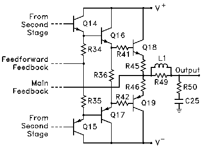
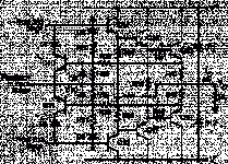
In this PDF you can find a layout:
An output-stage (OPS) based on NJL3281 and NJL1302
The circuit is this one. But parts values are missing:
An output-stage (OPS) based on NJL3281 and NJL1302
The circuit is this one. But parts values are missing:
Attachments
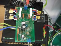
Hi..
What about this one?
I have readily available some LME49811 free samples and SAP15s.. Then this looks a good idea to make..
The BIAS input is for DC servo and TP1, TP2, TP3 are for the protection circuit which is also available in my drawer (the original new Crescendo amplifiers protection card)..
Its simple and will sounds good I think..
Do you have any comments or advices?
What about this one?
An externally hosted image should be here but it was not working when we last tested it.
I have readily available some LME49811 free samples and SAP15s.. Then this looks a good idea to make..
The BIAS input is for DC servo and TP1, TP2, TP3 are for the protection circuit which is also available in my drawer (the original new Crescendo amplifiers protection card)..
Its simple and will sounds good I think..
Do you have any comments or advices?
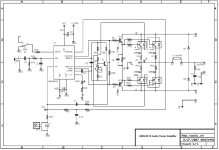
lineup said:The circuit is this one. But parts values are missing:
I am using the values shown below for the above tests.
Attachments
Sure..
This is the circuit;
Its not my design. Originally the Elektor's famous Crescendo Millennium amplifiers Protection & DC servo card..
I am using SAP as output device and they have exactly the same SOA curve as 2SK1530-2SJ201 which is the Crescendo's output devices. And the same emitter resistors that 0R22.. So I say why dont I use that circuit while available in my drawer..
This is the circuit;
An externally hosted image should be here but it was not working when we last tested it.
Its not my design. Originally the Elektor's famous Crescendo Millennium amplifiers Protection & DC servo card..
I am using SAP as output device and they have exactly the same SOA curve as 2SK1530-2SJ201 which is the Crescendo's output devices. And the same emitter resistors that 0R22.. So I say why dont I use that circuit while available in my drawer..
- Home
- Amplifiers
- Chip Amps
- LME49810 - a new cousin for LM4702