It can be a good idea though because it's not for certain tha t the amp will remain stable regarding the idle current.jackinnj said:Ivan -- you don't really need the Vbe multiplier if using the Renesas Lateral MOSFET's.
if the renesas Laterals are biased @ >=100mA/device pair then the negative temp co ensures that the bias is stable without requiring Bias temp compensation.
I have resistor biassed @ 75mA/device pair and even that lower bias shows a reduction in bias current as ambient temperature rises.
I have resistor biassed @ 75mA/device pair and even that lower bias shows a reduction in bias current as ambient temperature rises.
Does this happen with higher currents too, e.g. 250-500mA?AndrewT said:if the renesas Laterals are biased @ >=100mA/device pair then the negative temp co ensures that the bias is stable without requiring Bias temp compensation.
I was wondering how far up the current scale the assertion holds. If I upset you, I'm sorry.AndrewT said:>= means greater than or equal to.
Laterals become ever more negative temp co, the higher one takes the current.
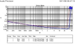
Look at the graphs.
Verticals generally don't become negative until above 6A to 12A and by then they have overheated with any sensible Vds.
Look at the graphs.
Verticals generally don't become negative until above 6A to 12A and by then they have overheated with any sensible Vds.
Hi Andrew and the others.
I've reading all topics dealing on lme49810 since i have on and i planed to use them for HT power blocs. I ve read all datasheet and application notes on LM4702, LME49810, and LME49830 (I will attends buiding something with these i have too later with IRFP240/9240 or 9140). Beside these i have a good stock of MJL3281/1302 and MJE1530/15031 (Andrew T you known this i mentioned in brother of quasi thread). The idea was to put them together in power channel for home theater. Here begin diffulties since i could'nt found à schematique cooresponding to what i was searching.
Ma dedicated room has 15m² surface. The speakers i planned to use have following specifications :
center : 91db/3,5 ohms min impedance
front lateral : 90db/6,0 ohms min impedance
suround : 88db/ 6,5 ohms min impedance
So i don't think I will need huge power amount (50/60w @ 8ohms will be sufficiant) but confortable current disponibility. I can have to a good price 330V 2x30 trafos.
I am be able to calculated the amount of Base current will be need for fixer bias current on output stage, but i don't really understood how we could set these base current through ajusting level voltage between Mbias/Pbias. I'am able to applicate ohms law with the 2,8mA Ibias but i don't find the relation between the voltage level at M/Pbais and Ib from outputstage. I have somme difficulties to manage the schematic with 2 ou 3 (if it's requierd) output bipolar and the "buffer" taht could provide the necessary amount of current requiered to drive multiple output transistors.
I found on diyaudio to schematic that could be a begin to my project :
Attachments
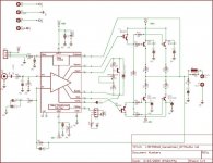
So my hope are tobring up a schematic that correspond to my requierements. Perahaps could that be achieved with the to above schematique with minor changes?
Marc
Marc
Specs on circuit parts
As a "newbie" to amp construction, could Forum members recommend specific parts for the simple amp design of the LME49810 shown on the vendors website?
http://www.national.com/pf/LM/LME49810.html
I'd like recommendations for:
Qmult; Q1, 2, 3, 4; heat sink for the LME49810.
Assume output of 150W into an 8 ohm load.
As a learning tool: how would I determine this?
Re: Specs on circuit parts
[QUOTEI'd like recommendations for:
Qmult; Q1, 2, 3, 4; heat sink for the LME49810.
Assume output of 150W into an 8 ohm load.
As a learning tool: how would I determine this? [/B][/QUOTE]
Would you like to try OnSemi ThermalTrak for output BJT? http://www.onsemi.com/PowerSolutions/product.do?id=NJL4281D.
I recommend you visit http://sound.westhost.com/articles.htm to find what you are looking for. I also highly recommend Douglas Self "The Audio Power Amplifier Design Handbook" http://www.dself.dsl.pipex.com/ampins/ampins.htm.
Have fun!
Re: Re: Specs on circuit parts
do include the dot at the end. Correct one:
http://www.dself.dsl.pipex.com/ampins/ampins.htm
do include the dot at the end. Correct one:
http://www.dself.dsl.pipex.com/ampins/ampins.htm
Re: Specs on circuit parts
I have used the inexpensive TIP142/147 for the output transistors -- a good resource is to look at Mark Brasfield's article on a high quality LM4702 design: http://www.national.com/an/AN/AN-1490.pdf He used MN2488 and MP1620 -- these you can get from MCM (Newark Electronics). He also used a TIP31 for the VBE Multiplier.
The ThermalTrak transistors aren't Darlingtons.
The LM4702 was the first of the high power driver chips and it now has a couple of brothers and sisters.
The heat sink calculation is a function of the worst-case load you will be running, supply rail voltages etc. This is the case where BIB. There's a good explanation of determining the correct heat sink value on the product folder for the LM3886, page 18 -- don't assume that your load is going to be as high as 8 ohms, however. http://www.national.com/ds/LM/LM3886.pdf The LME49810, LME4702 like to be kept cool as well, but in the amplifiers I have built with them I just use some spare PCB material attached to the chip.
marthaman said:As a "newbie" to amp construction, could Forum members recommend specific parts for the simple amp design of the LME49810 shown on the vendors website?
http://www.national.com/pf/LM/LME49810.html
I'd like recommendations for:
Qmult; Q1, 2, 3, 4; heat sink for the LME49810.
Assume output of 150W into an 8 ohm load.
As a learning tool: how would I determine this?
I have used the inexpensive TIP142/147 for the output transistors -- a good resource is to look at Mark Brasfield's article on a high quality LM4702 design: http://www.national.com/an/AN/AN-1490.pdf He used MN2488 and MP1620 -- these you can get from MCM (Newark Electronics). He also used a TIP31 for the VBE Multiplier.
The ThermalTrak transistors aren't Darlingtons.
The LM4702 was the first of the high power driver chips and it now has a couple of brothers and sisters.
The heat sink calculation is a function of the worst-case load you will be running, supply rail voltages etc. This is the case where BIB. There's a good explanation of determining the correct heat sink value on the product folder for the LM3886, page 18 -- don't assume that your load is going to be as high as 8 ohms, however. http://www.national.com/ds/LM/LM3886.pdf The LME49810, LME4702 like to be kept cool as well, but in the amplifiers I have built with them I just use some spare PCB material attached to the chip.
panson_hk said:Why use Darlington in audio amp? Space limitation? Cost?
You need the beta .
panson_hk said:Why use Darlington in audio amp? Space limitation? Cost?
then use a pair of darlington connected EF BJTs, making a three stage EF as used in many SS amps.jackinnj said:
You need the beta .
panson_hk said:Why use Darlington in audio amp? Space limitation? Cost?
Simplicity, fewer components.
Disadvantages:
- No control over internal topology (there are usually internal resistors in the Darlington).
- Non linear gain (beta) at low currents (=higher distortion compared with discrete). The Darlington doesn't turn on until a milliamp or so is fed into the base, and then a small incremental current turns it on much harder. ie. Hfe jumps from a couple of hundred to a couple of thousand.
- Can't use the EF Type II topology, with switch-off speed up capacitor (see fig 33 at http://www.dself.dsl.pipex.com/ampins/dipa/dipa.htm#5 )
Still, a credible amp can be built from them. I have designed and constructed a successful LM4702 + TIP142/147 amp.
There's also my 100W Class A effort of many years ago ( http://www.diyaudio.com/forums/showthread.php?threadid=32285 ) which uses 4 pairs of TIP142/147.
LM49810
Hi everybody,
I would like to know where can I find the Panson Poon part 2 design article.
I got the intersting "Using LME49810 to Build a High-Performance Power Amplifier - Part 1"
Thanks for help.
Franco
Hi everybody,
I would like to know where can I find the Panson Poon part 2 design article.
I got the intersting "Using LME49810 to Build a High-Performance Power Amplifier - Part 1"
Thanks for help.
Franco
Re: LM49810
Hi Franco,
Thanks for your interest! I haven't finished it due to my new bb and job. But I will continue....
Hi Franco,
Thanks for your interest! I haven't finished it due to my new bb and job. But I will continue....
- Home
- Amplifiers
- Chip Amps
- LME49810 - a new cousin for LM4702