This does not seem logical to me. Copper is hotter farther away from from the heat source? Can you elaborate on it or point to some reference information?Due to the lower thermal resistance of the copper cf aluminium, the copper will be hotter farther away from the heat source. These hotter areas (the fins) will be capable of dissipating more power.
The copper is a better heatsink, than if made in aluminium.
This does not seem logical to me. Copper is hotter farther away from from the heat source? Can you elaborate on it or point to some reference information?
what he wanted to say is cooper should be hotter more away than aluminium?
for the same external design, i.e. dimensions are all the same, then copper gives a better cooling effect, but it is much heavier and it is much more expensive.
Not to mention softer, which means threads would rip out easier.
I wonder what the relative performance of those two hypothetical heat sinks would look like if the aluminum was black anodized. Does anybody have data for how much that improves the thermal resistance?
~Tom
Some varnish and black paints are reputed to have higher emissivity than black dyed anodize (this affects radiation).
ESP quotes some data, but I have no idea how reliable it is.
Shiny and matt surfaces affect radiation emissivity.
The big advantage of anodise (but not dyed) is the low thermal resistance of the coating over the aluminium (this affects conduction). But that coating is not smooth (this affects convection). This roughness increases the thickness of the laminar layer and thus increases the thermal resistance between the anodise and the moving airstream.
If one dyes the anodize (conduction effect), the pockets get at least partially filled and the surface is smoother (convection effect). This may reduce the thickness of the laminar layer and make up for the increased thermal resistance of the dye (these two are a fight between conduction and convection).
There are three effects that make analysis quite complicated. Conduction, convection and radiation. How they are inter-related will have an effect on the overall thermal performance. It is not as simple as looking at only one of the three and picking the best of that one parameter.
Black copper oxide may be a good emissivity surface for copper. There is no equivalent for aluminium
Last edited:
This does not seem logical to me. Copper is hotter farther away from from the heat source? Can you elaborate on it or point to some reference information?
Let's assume identically-shaped heatsinks in identical ambient conditions (air). Both are mounted to identical chips dissipating the same amount of heat. One heatsink is made of copped, the other from aluminum. I'm also going to assume that the metal->air thermal conductance is the same.
In other words, we need to track how to move heat from the chip to the ambient air. Assuming steady-state, overall heat transfer (in watts) must be the same for both heat sinks. But we care about chip temperature, so we're trying to minimize the thermal impedance between the chip and the air. Temperature gradient is your voltage.
Copper's thermal conductivity is ~2x that of aluminum (per area, not per mass), ergo the thermal gradient from where the chip is mounted to the very tip of the fin will be less. This, in effect, makes the copper heat sink "bigger", as a greater amount of the fin area will be above ambient, rather than more of the heat loss happening in a smaller area with the heatsink.
Darn, that leaves me out..😕There are many on this forum that have formal training.
Doubly so.😀Some of them even excel at it.
As others said, the devil is in the details..it's always the units that get you..weight (or density) in this case.Thanks, but it seems heat capacitance is larger for aluminium than copper? Now I am confused.
When it comes to heat transfer, it is very important to understand the system and how the heat moves. At the chip, there is a very high thermal flux concentration. There, it is best to use materials which have very good thermal conductivity. Mica is NOT one of them, nor is epoxy, or silicone grease. Copper, silver, graphene are the best.
Directly under the die, the best thing to use is copper and graphene. Graphene only to fill the interstitial spaces between the copper backside of the package, and copper as the next component of the heat spread path.
Painting a heatsink is not bad, but only because the heat flux power density is much lower.. The thermal drop across paint or epoxy will be much lower if your dissipation density is watts per square foot. Directly under the die, the dissipation can be 1000 watts per square inch. There, it really matters what the thermal conductivity and contact surface finish is. That is a place you certainly would not want paint.
Jan...when?
jn
jneutron, that seems close to what I was thinking after looking at the heat capacitance data. Using copper to spread heat across aluminum, and let aluminum to dissipate heat. Probably plating an area with copper. Not sure whether aluminum can be plated like that or not.
jneutron, that seems close to what I was thinking after looking at the heat capacitance data. Using copper to spread heat across aluminum, and let aluminum to dissipate heat. Probably plating an area with copper. Not sure whether aluminum can be plated like that or not.
Along those lines: I have a CPU heat sink that has a round copper plug pressed into the aluminum heat sink. The copper is probably 25 mm in diameter and maybe 3-4 mm thick. The copper makes the thermal interface between the CPU die and the heat sink.
~Tom
Those CPU heat sink (HS) with Al/Cu are very efficient with coolers/fans compared to it's size.
You can find data for particular CPU for which of those heat sink is intended and find CPU's Tpd (Total Dissipation) so you can have some starting point about power.
Usually those CPU have Tpd in range 30-70W but can be more than 100W for some Xeon / PPC processors.
The reason for high efficiency of those HS is it's very large surface area!
Last edited:
Let's assume identically-shaped heatsinks in identical ambient conditions (air). Both are mounted to identical chips dissipating the same amount of heat. One heatsink is made of copped, the other from aluminum.
Copper is much more expensive than aluminium, and it has to be machined, not extruded, so for the same budget, the all-copper heatsink is going to be much smaller... aluminium wins on brute force. That's why cpu heat sinks use a copper slug in an easy to machine shape, coupled to an extruded aluminium heatsink.
Since the weak link is the silpad, one could take a bit of copper bar (say, 4x4cm, 5mm thick), solder the back of the chip on it, and put the silpad between the copper and the aluminium heatsink. That would get you more silpad area.
That thread is 14 years old. Not that I think the properties of copper or aluminium has changed the last 14 years 🙂
But what is it in that thread that is worth reading? I could not find any truth or any conducted tests.
But what is it in that thread that is worth reading? I could not find any truth or any conducted tests.
On packages like TQFP a heatsink can allow the chip to dissipate a few watts...
Thermal conductivities W/m.K
Copper : 380 ~ 400
Alu : 200 ~ 250
Silicon chip : 149
Epoxy Chip moulding compound 0.5 - 1
Yes, but alu has, pound for pound, over twice the heat capacity than copper. Therefore, for largely transient signals like music, alu has the distinct advantage of providing a larger buffer for heat. Otherwise said, it doesn't heat up quite as fast as copper for a given caloric input.
Yes, it can. However, if it's thin, as plating would be, it will not provide an advantage, merely another layer.jneutron, that seems close to what I was thinking after looking at the heat capacitance data. Using copper to spread heat across aluminum, and let aluminum to dissipate heat. Probably plating an area with copper. Not sure whether aluminum can be plated like that or not.
To really help the heatflow, the copper should have a good thickness between the chip and the aluminum. This is the concept behind a heat spreader. I elaborate on that concept in the LA article soon to be published.
Bingo. More silpad area gives lower heatflux density, hence lower delta T.Since the weak link is the silpad, one could take a bit of copper bar (say, 4x4cm, 5mm thick), solder the back of the chip on it, and put the silpad between the copper and the aluminium heatsink. That would get you more silpad area.
Yes, but alu has, pound for pound, over twice the heat capacity than copper. Therefore, for largely transient signals like music, alu has the distinct advantage of providing a larger buffer for heat. Otherwise said, it doesn't heat up quite as fast as copper for a given caloric input.
It is indeed confusing, this conductivity vs capacity vs diffusivity.
Copper will provide better transient buffering as well as better overall heatsink performance given the same form.
Copper, however, will be a heck of a lot heavier as well as very costly.
jn
Jan...when?
jn
Now 🙂
http://www.diyaudio.com/forums/ever...-linear-audio-publication-95.html#post4272057
On its way.
Jan
Cool. I cringe a bit responding within these threads, not quite sure how to handle it..😕
Is there a secret author handshake or sumptin??
jn
Copper is much more expensive than aluminium, and it has to be machined, not extruded, so for the same budget, the all-copper heatsink is going to be much smaller... aluminium wins on brute force. That's why cpu heat sinks use a copper slug in an easy to machine shape, coupled to an extruded aluminium heatsink.
Since the weak link is the silpad, one could take a bit of copper bar (say, 4x4cm, 5mm thick), solder the back of the chip on it, and put the silpad between the copper and the aluminium heatsink. That would get you more silpad area.
Yeah, I was just doing a thought experiment on copper vs aluminum. As you say, Cu is pretty cost prohibitive, so using it where it best counts (moving heat away from the chip) is the best recourse.
Or, of course, using ammonia-based heatpipes and really moving the heat away from the chip. 🙂
Cool. I cringe a bit responding within these threads, not quite sure how to handle it..😕
Is there a secret author handshake or sumptin??
jn
There's this thread.
Sorry for OT guys,
Jan
Thank you for the link.
Overclockinganonymous does indeed know his stuff. From his first post, I would certainly recommend any thermal advice he gives.
jn
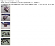
Just got some "cool" info from author (Macola) of those "controversial" metal parts for additional cooling of LM3886.
Take an look on picture …

You can believe in that or not, it is up to you. I believe them EVERY single words they say or write on our forum.
More readings on this link (Serbian language, try with Google translate):
Bato MM-Amp (LM-most by macolakg)
Take an look on picture …
It was checked because I have tried.
I would not be me if I did not examine what most can do a couple of LM3886🙂
With this method of cooling the chips dissipate continuous 100W !!! per chip for hours!
You can believe in that or not, it is up to you. I believe them EVERY single words they say or write on our forum.
More readings on this link (Serbian language, try with Google translate):
Bato MM-Amp (LM-most by macolakg)
Attachments
Last edited:
- Status
- Not open for further replies.
- Home
- Amplifiers
- Chip Amps
- LM3886 Thermal Experiment (with data)