Judging by the range of recommended thermal solutions for the LM3886 on this forum, there appears to be quite a bit of confusion on exactly how much heat sinking the LM3886 requires. I have written extensively about this on my website, Taming the LM3886 - Thermal Design, and I encourage anyone interested in the math and engineering behind proper thermal design to read that.
That said, I still found myself curious about exactly how small of a heat sink one can get away with. I also wanted to characterize the difference in thermal performance between the LM3886T (non-isolated) and the isolated LM3886TF. So I conducted an experiment...
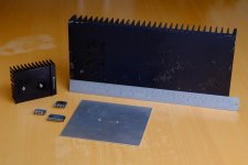
Three heat sinks:
Two types of LM3886:
Two thermal interfaces:
Supply voltage: ±28 V
Load impedance: 4 Ω
Now, I did not test all combinations of these as some combinations didn't make sense. For example, the LM3886TF can deliver the full rated 68 W when mounted on a 0.4 ºK/W heat sink, hence, the LM3886T will be able to as well. Similarly, the small sheet aluminum didn't provide much of a heat sink.
A 4 Ω load was used as this results in the highest amount of dissipated power in the LM3886.
Thermal limit: The LM3886 contains two circuits that protect the IC against failure at high temperature. The thermal protection circuit mutes the output once the die temperature reaches 165 ºC. The circuit un-mutes the IC once it has cooled to 155 ºC. In addition, the SPiKe protection circuit ensures that the output devices are operated within their safe area of operation (SOA), which includes temperature.
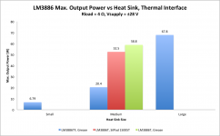
Test methodology: The LM3886 was attached to the heat sink and operated at the peak power dissipation (happens at 40.5 W output power into 4 Ω for an LM3886 operating at ±28 V) with a 1 kHz sine wave, continuously, until the heat sink temperature had stabilized. The output power was then adjusted until neither the SPiKe circuit nor the thermal protection circuit engaged (verified by watching the output voltage and distortion over time). The output power was noted as the maximum output power (see chart below) and the heat sink temperature was measured with an IR thermometer. Note that the IC operates at a die temperature just shy of 165 ºC under these conditions. Also note that the heat sink temperature reached 104 ºC before the thermal protection circuit kicked in.
Observations: I was surprised by the amount of power I could get out of the LM3886 when mounted on the Pentium Pro heat sink. It's a pretty small heat sink. A quick calculation puts its thermal resistance around 2.5 ºK/W. That is actually enough to allow the LM3886 to survive at peak power dissipation, though, as soon as the furnace in my house kicked on and raised the temperature of the room slightly, the thermal limiter tripped. Also, the SPiKe protection kicks in once the output power approaches 50-60 W. The heat sink temperature reaches 104 ºC, so this is definitely not a safe arrangement for an external heat sink. However, a CPU heat sink with a fan (and fan controller to keep it quiet when there's light thermal load) seems like a pretty viable solution.
The large, 0.4 ºK/W heat sink reached 43 ºC when operated at the peak power dissipation. The ambient temperature was 20 ºC.
For an external heat sink, where a maximum temperature of 60 ºC should be enforced, a 0.8 ºK/W rated heat sink is needed for sine wave operation. This was estimated from the temperature rise of the 0.4 ºK/W heat sink and is in line with the math on my website.
Edit 19 MAR 2015: Latest data available in Post #36.
Edit 12 SEP 2020: Link to LM3886 cross-sections:
~Tom
That said, I still found myself curious about exactly how small of a heat sink one can get away with. I also wanted to characterize the difference in thermal performance between the LM3886T (non-isolated) and the isolated LM3886TF. So I conducted an experiment...
Three heat sinks:
- "Small" = 13x13 cm aluminum sheet, 1.6 mm thick.
- "Medium" = Pentium Pro heat sink (Compaq P/N: 219222-006 NNE)
- "Large" = Heat sink specified at 0.4 ºK/W (about 2 kg of aluminum!)
Two types of LM3886:
- LM3886T - non-isolated package.
- LM3886TF - isolated package.
Two thermal interfaces:
- "Grease" = Wakefield 120 thermal compound.
- "SilPad 1500ST" = Bergquist SilPad 1500ST.
Supply voltage: ±28 V
Load impedance: 4 Ω
Now, I did not test all combinations of these as some combinations didn't make sense. For example, the LM3886TF can deliver the full rated 68 W when mounted on a 0.4 ºK/W heat sink, hence, the LM3886T will be able to as well. Similarly, the small sheet aluminum didn't provide much of a heat sink.
A 4 Ω load was used as this results in the highest amount of dissipated power in the LM3886.
Thermal limit: The LM3886 contains two circuits that protect the IC against failure at high temperature. The thermal protection circuit mutes the output once the die temperature reaches 165 ºC. The circuit un-mutes the IC once it has cooled to 155 ºC. In addition, the SPiKe protection circuit ensures that the output devices are operated within their safe area of operation (SOA), which includes temperature.
Test methodology: The LM3886 was attached to the heat sink and operated at the peak power dissipation (happens at 40.5 W output power into 4 Ω for an LM3886 operating at ±28 V) with a 1 kHz sine wave, continuously, until the heat sink temperature had stabilized. The output power was then adjusted until neither the SPiKe circuit nor the thermal protection circuit engaged (verified by watching the output voltage and distortion over time). The output power was noted as the maximum output power (see chart below) and the heat sink temperature was measured with an IR thermometer. Note that the IC operates at a die temperature just shy of 165 ºC under these conditions. Also note that the heat sink temperature reached 104 ºC before the thermal protection circuit kicked in.
Observations: I was surprised by the amount of power I could get out of the LM3886 when mounted on the Pentium Pro heat sink. It's a pretty small heat sink. A quick calculation puts its thermal resistance around 2.5 ºK/W. That is actually enough to allow the LM3886 to survive at peak power dissipation, though, as soon as the furnace in my house kicked on and raised the temperature of the room slightly, the thermal limiter tripped. Also, the SPiKe protection kicks in once the output power approaches 50-60 W. The heat sink temperature reaches 104 ºC, so this is definitely not a safe arrangement for an external heat sink. However, a CPU heat sink with a fan (and fan controller to keep it quiet when there's light thermal load) seems like a pretty viable solution.
The large, 0.4 ºK/W heat sink reached 43 ºC when operated at the peak power dissipation. The ambient temperature was 20 ºC.
For an external heat sink, where a maximum temperature of 60 ºC should be enforced, a 0.8 ºK/W rated heat sink is needed for sine wave operation. This was estimated from the temperature rise of the 0.4 ºK/W heat sink and is in line with the math on my website.
Edit 19 MAR 2015: Latest data available in Post #36.
Edit 12 SEP 2020: Link to LM3886 cross-sections:
~Tom
Attachments
Last edited:
The TF does not like continuous duty.
I knew it was poor, but the National data never gave me the clue it was that bad.
But since that does not apply to music reproduction then it is almost irrelevant.
I recommend that average listening levels be set to ~10% (by voltage) of the maximum output levels.
i.e. select an amplifier that has 100times the power output compared to the power one actually listens to.
That ensures the amplifier never sees continuous duty at maximum output levels and the heatsink never gets up to the temperatures predicted for maximum continuous duty.
BTW, with the speakers I regularly use, I find that average speaker voltage is around 100mVac to 2Vac (into 8ohms)
That requires amplifier power of around 50W into 8ohms.
If I want it louder I change amplifier, or change speaker.
Last edited:
The labeling should reflect what you are testing.
I see you are testing for continuous maximum power until some "trigger" point limits the continuous maximum power being measured.
Continuous has been omitted from the Thread title and from the diagrams. This is misleading.
I see you are testing for continuous maximum power until some "trigger" point limits the continuous maximum power being measured.
is mentioned in the script.continuously,
Continuous has been omitted from the Thread title and from the diagrams. This is misleading.
Nice experiment. I always wondered why anyone would choose the LM3886TF, now I have absolutely no idea. ")
This agrees with what most people use. Amplifiers of about 100W and a listening level of about 1W average.AndrewT said:select an amplifier that has 100times the power output compared to the power one actually listens to.
Nice experiment. I always wondered why anyone would choose the LM3886TF, now I have absolutely no idea.
I chose isolated, because it is easier to mount. No nylon screws required. As it is nearly impossible to overheat it with normal music, then why should I chose a not insulated one?
"select an amplifier that has 100times the power output compared to the power one actually listens to."
man, i think You did not mean more than 10 times...
those of us who live alone like it louder than others,
for me .. i ouwld need a 800 watt amp if I'd follow that instruction.
man, i think You did not mean more than 10 times...
those of us who live alone like it louder than others,
for me .. i ouwld need a 800 watt amp if I'd follow that instruction.
The TF does not like continuous duty.
That's not true. The LM3886 doesn't mind continuous duty at all. It just needs a larger heat sink than the LM3886T to support the power.
Note that the LM3886TF was actually able to deliver the full 38 W into 8 ohm on the "small" heat sink (13x13 cm, 1.6 mm thick aluminum sheet). I forget what the heat sink temperature ended up at. I can look that up when I get home.
The labeling should reflect what you are testing.
I see you are testing for continuous maximum power until some "trigger" point limits the continuous maximum power being measured.
Gimme a break. It's mentioned clearly in the text.
I chose isolated, because it is easier to mount. No nylon screws required. As it is nearly impossible to overheat it with normal music, then why should I chose a not insulated one?
BINGO! It's much easier to mount. That's why you'd choose the isolated version.
Never use nylon screws for anything involving device mounting, by the way. Nylon stretches. Use the isolating shoulder washers intended for TO-220 packages and metal machine screws.
There could also be a test with a normal music signal, full power just before speakers start to distort.
You would first have to decide on what constitutes "normal" music. If "normal" music is highly compressed heavy metal with a crest factor of 6 dB, you'll be operating the amp at the peak power dissipation and can apply my results directly. If your idea of "normal" is well-recorded classical music, you'll be looking at a 20 dB crest factor (i.e. a 100:1 ratio between peak and RMS power) which is in line with what Andrew suggests.
You can read more about this on my Taming the LM3886 - Thermal Design page.
~Tom
..................Continuous has been omitted from the Thread title and from the diagrams. ............
Yes, it's in the text................. It's mentioned clearly in the text.
....................
It is not in the title, nor on any of the diagrams.
The TF does not like continuous duty.
I knew it was poor, but the National data never gave me the clue it was that bad.......................
Have I mis-read the data.That's not true. The LM3886 doesn't mind continuous duty at all. It just needs a larger heat sink than the LM3886T to support the power...........LM3886TF was actually able to deliver the full 38 W into 8 ohm..........
You show 20.4W for the TF vs 52.5W & 58.8W for the T version using your test set up and continuous duty.
Are you saying something else?
I did not see 38W for the TF anywhere.
Last edited:
You show 20.4W for the TF vs 52.5W & 58.8W for the T version using your test set up and continuous duty.
On the Pentium Pro heat sink ("medium"), the TF provides 20.4 W RMS continuously into 4 Ω. This means it'll survive use for music reproduction, assuming a crest factor of >6 dB. Of course, the heat sink will get screaming hot, but the IC will survive. Just a few posts ago, you argued that a 20 dB crest factor should be used. The TF will barely break a sweat under those conditions if fitted to the Pentium Pro heat sink.
The TF version provides the full 68 W on the "large" 0.4 ºK/W heat sink. That's in line with National/TI's specs. I don't see how this renders the chip useless or somehow inferior to the T version as you mentioned earlier.
I did not see 38W for the TF anywhere.
I did not present any 8 Ω data as it wasn't very exciting. The TF version will provide the full specified 38 W into 8 Ω when fitted to the "small" heat sink (130x130x1.6 mm aluminum sheet). When operated at the peak power dissipation, continuously with a sine wave signal, 8 Ω load, ±28 V supply, the "small" heat sink reaches 91 ºC. Just before clipping (Pout = 38 W), the heat sink reaches 82 ºC.
Given the data presented it's being pretty pedantic to gumble about that.
Apparently the nits are good pickin' this time of year...
No good deed ever goes unpunished, I guess. Oh, well. I prefer to contribute to the DIY community by providing data and insight. Others are free to differ.
~Tom
Last edited:
Nice !
I'm interested in your estimation of the thermal resistance of this 1.6mm aluminium sheet, because I intend to use the front plate of the case as a heatsink for my regulators. That's because the front side of a case usually sees open air, whereas the back or sides generally see the inside of furniture or are buried in cables.
I'm interested in your estimation of the thermal resistance of this 1.6mm aluminium sheet, because I intend to use the front plate of the case as a heatsink for my regulators. That's because the front side of a case usually sees open air, whereas the back or sides generally see the inside of furniture or are buried in cables.
Excellent info, Tom. Thank you.
Your use of the Pentium Pro heat sink is very helpful, since I have a box of old CPU heat sinks that will no doubt be rummaged through when it comes time to build my Modulus-86 amp. From what I remember, I have several that are much more capable than that Pentium Pro heat sink.
When I factor all that together in my head, along with the fact that I will rarely ask the amp to push much more than a few watts continuous, I'm pretty comfortable ordering the TF version of the 3886.
I'm interested in your estimation of the thermal resistance of this 1.6mm aluminium sheet
The 130x130x1.6 mm aluminum sheet comes in around 3.3 ºK/W.
The Pentium Pro heat sink, 2.0 ºK/W.
Both figures at a temperature differential between the heat sink and ambient of about 80 ºC.
Be careful when attaching components that dissipate a lot of power to the chassis - or any metal surface exposed to the user. Heat causes burns... Just saying.
~Tom
Yeah... the plan is to dissipate 10W or less, split between several transistors, so it should be OK.
Also with 1.6mm thickness only you'll probably get a hotspot where the LM3886 is mounted, did you measure the temperature at various points or only at the LM3886 mounting point ?
Perhaps adding a simple heat spreader (like this 6mm thick one) between LM3886 and heatsink would reduce the hotspot and thermal resistance...
- Status
- This old topic is closed. If you want to reopen this topic, contact a moderator using the "Report Post" button.
- Home
- Amplifiers
- Chip Amps
- LM3886 Thermal Experiment (with data)