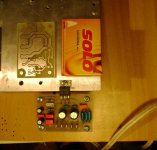
New Board
Thanks Andrew for the reply
I have added high pass filter at the input in ZR & ZC both with values ????, I think I have got the formula for calculation of corner frequecy wrong, can you suggest the values for ZR & ZC for lowest possible Fz
in both the boards LM3886 & LM1875 speaker ground returns to Power Ground, and power ground is joined to signal ground via 10R/2W resistor in case of LM1875 PCB and 10R/2W parallel with 0.1uF/63V on LM3886 board.
I have not seen any PCB with LM3886 decoupled with 0.1uF capacitor, if need be I will mount them under the PCB on legs of IC
Regards
Yatin
we are getting there.
Now add the High pass filter at the input.
This will convert the amplifier to AC coupled.
I like the differentiation between GNDa and GND.
What about the speaker return?
I would expect pin5 to require decoupling.
National do not expressly say which or if both supplies need decoupling.
Thanks Andrew for the reply
I have added high pass filter at the input in ZR & ZC both with values ????, I think I have got the formula for calculation of corner frequecy wrong, can you suggest the values for ZR & ZC for lowest possible Fz
in both the boards LM3886 & LM1875 speaker ground returns to Power Ground, and power ground is joined to signal ground via 10R/2W resistor in case of LM1875 PCB and 10R/2W parallel with 0.1uF/63V on LM3886 board.
I have not seen any PCB with LM3886 decoupled with 0.1uF capacitor, if need be I will mount them under the PCB on legs of IC
Regards
Yatin
Attachments

pins 1 & 5 are shown commoned to V+ with Cs as decoupling. National specify Cs as including 100nF.I have not seen any PCB with LM3886 decoupled with 0.1uF capacitor, if need be I will mount them under the PCB on legs of IC
Thanks Andrew
I need to rephrase my last line in post 221. It should be read as
"I have not seen LM3886 leg 5 separately decoupled with 0.1uF capacitor"
as leg 1&5 are jumpered and deocoupled with 0.1uf Capacitor, I think it will be OK.
as for the question on the R & C values for input filter, can you suggest the values, or the formula for calucation of the corner frequency? I am using Fo = 1/(2 x pi x R x C) both R & C values in Ohm and Farads respectively.
Thanks
Yatin
I have found that F-3dB about ten times lower than the lowest frequency required from that amplifier gives good bass.
I have also found that this ten times applies when a reduced bandwidth is required for a Mid or Treble driver amplifier.
If your lowest audio is 20Hz then F-3dB should be 2Hz, if you follow the above.
I do the same for the HF end of the audio spectrum.
F=1/2PiRC is the correct equation.
Setting the input filters for F-3dB to 2Hz and 200kHz results in +0-1dB bandwidth of 4Hz to 100kHz.
There is much flexibility in choosing these frequencies to suit your equipment and your ears.
Thanks Andrew
Proposed to use ZR=47K ohm & ZC=0.47uF this will give F-3db at 7Hz, and this will filter out any frequency below 70Hz, inlcuding 50~60Hz AC power hum ? (India the AC power is 220V at 60Hz)
Thanks & Regards
Yatin
Proposed to use ZR=47K ohm & ZC=0.47uF this will give F-3db at 7Hz, and this will filter out any frequency below 70Hz, inlcuding 50~60Hz AC power hum ? (India the AC power is 220V at 60Hz)
Thanks & Regards
Yatin
no.Proposed to use ZR=47K ohm & ZC=0.47uF this will give F-3db at 7Hz, and this will filter out any frequency below 70Hz, inlcuding 50~60Hz AC power hum ?
Setting F-3dB to 7Hz will allow frequencies of 70Hz and above to pass with almost no attenuation.
60Hz will be attenuated by a tiny amount.
If you want to attenuate 60Hz then F-3dB should be set to >=600Hz, but that is preposterous for an audio amplifier.
Thanks Andrew
Then it raises another point, whether ZR ZC filter is necessary at the input
Is it a electrical requirement or sonic requriement
Pardon my ignorance
Regards
Yatin
Then it raises another point, whether ZR ZC filter is necessary at the input
Is it a electrical requirement or sonic requriement
Pardon my ignorance
Regards
Yatin
yes, it is required.
It is the DC block and it is the high pass filter.
These are needed for electrical performance and for audio performance.
The one capacitor does a variety of jobs.
It's disadvantage is that it interferes with the wanted audio signal passing through the amplifier. This interference must be minimised for optimum audio quality.
Omitting this cap is an option, but the design of correction and protection systems must be followed through to prevent bad audio transmission and equipment damage.
Some interesting tricks for LM1875 Active Speaker:
10k input load and 15k* feedback resistor
Overbuilt power supply or regulators
NFB bandwidth about an octave lower than input bandwidth
The bass roll off of the input and NFB can be aimed at the corner frequency of the woofer to do less of what the woofer can't do, thus causing it to do more of what it can (corner frequency manipulation).
In this example, the feedback resistor could be 10k for most bass or 18k for most treble or anywhere in-between, with the small caveat that changing the feedback resistor will cause you to have to re-calculate gain settings and also NFB cap bandwidth.
However, some speakers don't respond to this. Full range speakers like Lowther, Fostex and similar seem to require vacuum tubes. But they don't. What they require is current drive in order to achieve their advertised speaker driver frequency response. One-third of the way down this page --> Dial-A-Tube <-- is Lenard Audio's Variable Current drive application for power op-amps. There's also a power supply that exploits larger value resistors in the PI filter section of the power supply, making a form of soft clip (hoping I read that right). So, theoretically, you could make an LM1875 "Dial-A-Tube" preamp (class A or AB), headphone amp, (class A or AB), or power amp (class AB).
There are other designs possible, such as class ABC symmetry (armstrong boost) for 100w or class H/G for 500w or 1kw. However, at some point, it would become more cost effective to purchase either additional speakers (along with additional LM1875's too) or more-efficient speakers. 🙂
I just wanted to point out that LM1875 can be used in many different designs.
Hello.
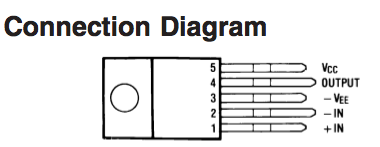
I considering making the LM1875 for some practice. I've just been looking at the data sheet and more specifically the IC pins. According to the datasheet, pin 3 is Vee and Pin 5 is Vcc. Now I am a newbie but as I undrstand Vcc is the positive voltage rail and Vee is the negative voltage rail?
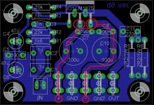
Looking at the PCB diagram above, specifically the + and - symbols at the bottom, and assuming that the IC pins run from 1 -5 left to right, the middle pin (3) track goes to positive voltage input and furthermost right pin (5) track goes to negative voltage input which is the opposite way round to the datasheet.
If I'm wrong about this then let me know, as like I said, I'm relatively new to this with only a couple of simple builds under my belt!
Thanks,
John
I considering making the LM1875 for some practice. I've just been looking at the data sheet and more specifically the IC pins. According to the datasheet, pin 3 is Vee and Pin 5 is Vcc. Now I am a newbie but as I undrstand Vcc is the positive voltage rail and Vee is the negative voltage rail?
Looking at the PCB diagram above, specifically the + and - symbols at the bottom, and assuming that the IC pins run from 1 -5 left to right, the middle pin (3) track goes to positive voltage input and furthermost right pin (5) track goes to negative voltage input which is the opposite way round to the datasheet.
If I'm wrong about this then let me know, as like I said, I'm relatively new to this with only a couple of simple builds under my belt!
Thanks,
John
Attachments
Last edited:
Hey Andrew.
I understand that but if you look at Millano's PCB layout diagram, the track marked as positive is running to pin 3 and the track marked as negative is running to pin 5...shouldn't the symbols be the other way round?
I'd also be interested what you think of the layout as a whole?
John.
I understand that but if you look at Millano's PCB layout diagram, the track marked as positive is running to pin 3 and the track marked as negative is running to pin 5...shouldn't the symbols be the other way round?
I'd also be interested what you think of the layout as a whole?
John.
Attachments
Hi,
well spotted, the labels at the PCB edge have been accidentally swapped.
The proposed RF filter is set to cut some of the audio band.
RC time constant =1.5us (R=1k5, C=1nF).
This is F-3dB @ ~100kHz and F-1dB @ ~50kHz.
You may not like the sound of this. Leave the 1nF cap on very long leads or even temporary tacked onto the bottom side of the PCB and listen to it's effect.
Change it to 680pF and to 470pF to hear the difference. You might even prefer going to 330pF.
I don't like the RC (23.5ms) of the DC block (R=1k0, C=47/2uF). It is set to double the frequency of the input filter. I recommend that you try one 100uF and 150uF here. Link across the empty cap location. Measure the DC voltage on this cap once you have the output offset adjusted to near zero millivolts DC. Expect +-30mVdc to +-150mVdc. Fit a diode across the cap terminals (on the bottom side). Arrange the +ve of the diode to match the +ve of the capacitor. This prevents the capacitor becoming reverse biased if the amplifier ever fails.
Last edited:
pls
hey daniel!am a newvie...pls help me out with 5 watts tweeter amp with dc protection...am on a project for tri amping.....cud it de tda or 1875!??Pretty job there!!!
Hi Milano,
That was a great PCB. Pls mail me the PCB files if U can as I would like to make this to replace my current 2.1 system in which one channel is dead. Although the PCB is relatively simple even to hand make , I would still prefer to get it made from a fab house in case I need to make some more. Thanks Andrew T , I belive I shall incorporate your suggestions too .
I notice this thread is quite old and Iam not sure if there is any further interest in the topic anymore... Anyway Iam posting this just in case Milano is still out there listening.
Thanks in Advance...🙂
Ravi Rao ( ravi.rao.kumar@gmail.com )
Mumbai-India
- Status
- Not open for further replies.
- Home
- Amplifiers
- Chip Amps
- LM1875 PCB, Which To Use