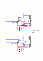
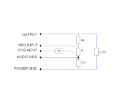
You could place the GLB between the Audio Grounds and Power Ground, one per channel. In this configuration the resistor is also part of the feedback loop and the diodes are there to protect the resistor. If the resistor fails the output will go to full negative rail voltage.
The My_Ref amps have a similar layout but without the diodes. The resistors do fail and activate the speaker protection.
The My_Ref amps have a similar layout but without the diodes. The resistors do fail and activate the speaker protection.
maybe your copper wire is hard drawn.Not easy at all 😡..............
Andrew, I cannot twist wires, ptfe is too hard, and solid copper also, mostly for a very short distance.
......
Enameled is usually annealed and thus comes relatively soft until you work harden it.
I have noticed that CAT5 copper is much harder than both hook up wire and enameled copper wire. I suspect CAT5 is specified as a hard drawn and not annealed copper.
You must reduce that LOOP AREA in the input circuit.
Last edited:
Andrew you are right..
Little ot about wires, I have a lot of different sizes or metals wires, all are cryogenic..
I sent wires in UK for treatment :
Frozen Solid
Electrical and mechanical specs was changed by cryo, more conductivity for example..
It's used for brake car, and by musicians too, for trumpets or strings guitar.
I try it with my diy stick bass (two strings), sounding is more "loud" more deep.
For audio cable, my personal opinion is a little better at sounding, but some guys said it's like snake oil. It is not obvious, but a little more, and a little more, can give a big difference at concluding.
It costs a bit, but it's my pleasure..
Phil.
Okay, so use the resistor, the diodes, AND add the 100n. 🙂
Ok, but how to make wiring ?
See below a proposal.
Attachments
No.
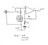
The feedback R3+C: connects to R2 and also to input return/cold.
This Loop Input Hot to R2 to +IN to bottom of R2 to bottom of C: to input cold MUST be ultra low LOOP AREA.
If you can get Rf & -IN and top of R3 also with very low Loop area then that too reduces interference effects.
Although we don't have the details, this is almost certainly what Tom had to do to get the exemplary performance from his composite amplifier.
The bottom of the Disconnecting Network (DN) connects to the Main Audio ground.
It is the voltage reference connection between the Output and the Input and passes almost zero signal current. You will probably not be able to measure the Vdrop across the DN.
Has anyone used a +80dB LNA (Low Noise Amplifier) to measure the currents (signal & interference) across the DN?
Last edited:
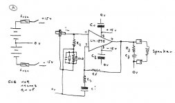
Try to understand the circuit. Place the GLB between the audio ground (input and feedback) and the power ground (PSU , Zobel and speaker).
Trace the different current paths, like input, output, feedback, power supply and any ground loops.
Trace the different current paths, like input, output, feedback, power supply and any ground loops.
The feedback current flows between the audio ground and the power ground.
The feedback loop is output->Rfb->Ri->Rglb->power ground and is parallel to the output load.
The feedback loop is output->Rfb->Ri->Rglb->power ground and is parallel to the output load.
Mark,
Thank's a lot, simple and easy for soldering !
I keep the 0,1 uF in GLB like Daniel said.
I will finish tomorrow amp ..
Phil.
Thank's a lot, simple and easy for soldering !
I keep the 0,1 uF in GLB like Daniel said.
I will finish tomorrow amp ..
Phil.
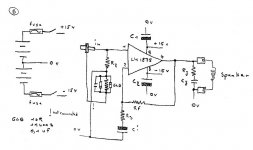
Part of the "fun" of P2P is that you can learn.
Try to understand what each part does and how the layout can also change the circuit.
Redrawing the schematic can sometimes give you a different perspective.
Here you can see the feedback current route and how it relates to the output voltage. You can also see the ground loop path.
Try to understand what each part does and how the layout can also change the circuit.
Redrawing the schematic can sometimes give you a different perspective.
Here you can see the feedback current route and how it relates to the output voltage. You can also see the ground loop path.
Attachments
Hi,
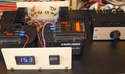
Dc offset is near 0 after 2 seconds, without load..
I will test later with speakers and music.
Yes Mark, P2P is not easy to build and for wiring, but I learn more about ground loop, 0 volt, breaker and so.. Very instructive.
Not realy a nice amp, but I consider it like a prototype 🙂
I ordered new batteries, today it's old..
Phil.
An externally hosted image should be here but it was not working when we last tested it.
Dc offset is near 0 after 2 seconds, without load..
I will test later with speakers and music.
Yes Mark, P2P is not easy to build and for wiring, but I learn more about ground loop, 0 volt, breaker and so.. Very instructive.
Not realy a nice amp, but I consider it like a prototype 🙂
I ordered new batteries, today it's old..
Phil.

You can, I'm sure you want same 😀I'm jealous.. It's beautiful! 😉
And it's works well, it looks a bit like LM3875 "low power"..
At 6 Ohm load, DC offset is 2 mV, heatsinks stay very cold, 25° for 22° in room.
Just a small defect, a little "ploc" when I switch off.. But not dramatical..
Phil.
Attachments
Cool project. I am thinking of doing something similar for sound systems near my hot tub and near my outdoor lounge area. I will probably use components similar to the ones that OffGridKindaGuy used, and class D amps. I bought 5 of those cheap bluetooth adapters for $20 and I can't believe how well they work for the money.
Best of luck with the rest of the project, Phil.
Best of luck with the rest of the project, Phil.
Hi,
Just a little problem when I switch off amp, a little "plic" (not "ploc") was create in speakers.
Actually it's Nicd, Li Ion are better (in particular for bass), I think that Li Ion can give a big courant in a very short time, better than other kind of battery.
Someone has already noticed this ?
Phil.
Thank's, I waiting the new Li Ion batteries, smallest, and which will not exceed the case..Best of luck with the rest of the project, Phil.
Just a little problem when I switch off amp, a little "plic" (not "ploc") was create in speakers.
Actually it's Nicd, Li Ion are better (in particular for bass), I think that Li Ion can give a big courant in a very short time, better than other kind of battery.
Someone has already noticed this ?
Phil.
Input noise. Possibly need the IN+ base stopper in series with the input coupler, like this:
cap > base stopper (that's a resistor), input load, amp
Your amplifier is trying to correct the difference between the dividers located at in+ and in-, which it can certainly do except during power on/off conditions. (WHAM!!!)
alternative ordering is:
cap> input load> base stopper> amp
You might have to try both possibilities to get the power thumps stopped.
edit:
Then again, any speaker worth playing loud has far more than enough current handling capacity for a power on/off thump. My gosh. My poor speakers get a lot more than that during normal replay. Sometimes I feel sorry for them. But, their longevity seems excellent and they're obviously very tolerant of horseplay. 😀 So, I think that the little power thump issue is strictly unimportant, unless you're designing an amp for resale.
Last edited:
Daniel,
Just found the problem, one bat is dead !
With load, I have one side 15,2 volt and other side 13,8 volt !
I hope with new bat, both rail are same voltage when discharge operate.
Phil.
Just found the problem, one bat is dead !
With load, I have one side 15,2 volt and other side 13,8 volt !
I hope with new bat, both rail are same voltage when discharge operate.
Phil.
- Status
- Not open for further replies.
- Home
- Amplifiers
- Chip Amps
- LM1875 P2P "solar powered"