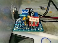
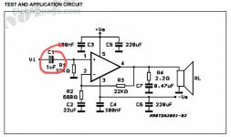
You can see the position of the input 10uF cap in post #132 and should have 2 holes open towards the heatsink and not 3. It's in the wrong spot.
Also double check your power supply etc.
Also double check your power supply etc.
First put black test probe touching ground as Mooly explained, which is also the screw labelled "G" on the supply terminal block.I can not understand well, try to explain it again, there. power supply ground ok but then which pins? have patience
Then touch pins 1 - 2 - 3 - 4 - 5 at the chipamp itself with the red probe, multimeter set to DC, and post voltges found.
We "expect"
1: almost 0V . Finding, say, 5 or 10mV is no problem.
2: almost 0V . Finding, say, 5 or 10mV is no problem.
3: negative supply voltage. -17V
4: almost 0V . Finding, say, 20 to 50mV is no problem. Even 100mV would not be worrying.
5: positive supply voltage. +17V
Only that please, then we may check other things.
Ecco
Pin 1:. 001,0 mv
Pin 2:. 000,5 mv
Pin 3:. 17 volt
Pin 4:. 001,6 mv
Pin 5:. 16,9. Volt
now I'm going to change the position of that 10u capacitor
Pin 1:. 001,0 mv
Pin 2:. 000,5 mv
Pin 3:. 17 volt
Pin 4:. 001,6 mv
Pin 5:. 16,9. Volt
now I'm going to change the position of that 10u capacitor
Ragazzi vi amo,ora funziona.
Siete stati fantastici.
Grazie
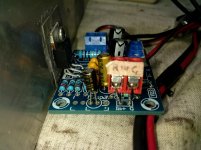
Metto le foto dell'errore prima e dopo.
Chissa' cosa sbagliavo in precedenza,forse la stessa cosa,mi sa che invertivo la polarità
Di quel condensatore.
Vi bacio a tutti
Siete stati fantastici.
Grazie
Metto le foto dell'errore prima e dopo.
Chissa' cosa sbagliavo in precedenza,forse la stessa cosa,mi sa che invertivo la polarità
Di quel condensatore.
Vi bacio a tutti
Attachments
Una cosa volevo chiedervi , :quale Polarità deve avere quel condensatore?
Perche' a volte la trovo in un modo a volte in un altro.
Perche' a volte la trovo in un modo a volte in un altro.
Attachments
Last edited:
So is it working now?
(you need to be very precise with detail on voltage measurements 🙂 The readings in post #164 show that the amplifier can not possibly work... but I'll let you think on 'why' that might be the case 😉)
(you need to be very precise with detail on voltage measurements 🙂 The readings in post #164 show that the amplifier can not possibly work... but I'll let you think on 'why' that might be the case 😉)
yes mooly ,it works, even if the sound is slightly distorted,
the measurements I made with the capacitor mounted wrong
the measurements I made with the capacitor mounted wrong
..........................Ecco
Pin 1:. 001,0 mv
Pin 2:. 000,5 mv
Pin 3:. 17 volt
Pin 4:. 001,6 mv
Pin 5:. 16,9. Volt you mean MINUS 16,9 Volts 🙂
now I'm going to change the position of that 10u capacitor
......................Guys I love you, now it works.
You are GREAT, thanks
Post before/after error picture.
Previous mistake was I had inverted that capacitor
Kisses to all.
In truth, it´s the same both ways (in that case) because it has no DC applied ; although it is NOT bipolar, it can stand small Audio voltages with no problems.One last question, which polarity should that capacitor have?
because sometimes I find it one way, sometimes the other
I GUESS you had some soldering error which you corrected when inverting the capacitor.
Good luck. 🙂
yes mooly ,it works, even if the sound is slightly distorted,
the measurements I made with the capacitor mounted wrong
Well that's good 🙂
The sound should not be distorted but you would really need an oscilloscope to delve much further into it.
mi sbagliavo non era una distorsione,ma un altoparlante rovinato che faceva rumore.
Anzi questo chip suona molto bene,mi piace.
ora sto usando un preamplificatore con 2 ne5534,ma ne ho molti altri da provare.
Anzi questo chip suona molto bene,mi piace.
ora sto usando un preamplificatore con 2 ne5534,ma ne ho molti altri da provare.
The direction of a polar input capacitor is shown on the PCB with a + symbol.
If you are getting distortion with these modules you are either over driving it or the power supply is not robust. ±17VDC may be a bit low (gives about 11W) and I use ±21-26VDC on these modules with genuine LM1875 chips. I did try a low current ±15VDC which distorted early. For each module you need around 50VA and minimum of 2200uF caps per rail.
When assembling these modules in an amp, here's a sequence I go through to ensure it goes smoothly.
* Check the power supply is giving the correct ± DC voltage and the ground also goes to the mains earth for safety.
* Mount the LM1875 on the heatsink with isolation pads (Mica + compound or Silicon) and isolation bush under the mounting screw head. Check with DMM to ensure no continuity between the heatsink and module. Ground the heatsink.
* Attach the power supply, short the input connection (hot to cold) and check the ± DC voltages on the power in and then if OK check the DC offset across the speaker output terminals. Should read less than 20mV and on these I've found found them to be less then 4mV.
* If not, recheck but if OK then ready to add a source and attach the speaker for testing.
ciao rabbitz,si in effetti l'alimentatore è un po deboluccio,lo ho usato per paura di far saltare i vari chip che provavo .pensi che un 18 volt ac raddrizzato possa andare meglio?
Last edited:
Hi
If the google translation is correct.🙂
yes.... a AC 18V-0-18V Transformer 100VA(120VA) gives you an good power. after rectifier you will get at this amp modules 18V*1,40 = 25,2V.
you can use a 15V-0-15V 100VA(120VA) too -then you get about 21 Volts after rectifier.
For the PSU you have to use about 2200µF caps in minimum (better4700µF) for each rail.
do these steps as rabbitz wrote ....and re solder everthing.
chris
ok, the transformer is a linear 18 volt ac, but i also have a 17 volt toroidal, i always talk about unrectified alternating current, which one do you think is better?
- Home
- Amplifiers
- Chip Amps
- LM1875 non funziona