I bought some pcb already made, I mounted one this morning and the incredible thing is that this one doesn't work either, always with the same problem.
So maybe we should be suspecting your LM1875 chips. There isn't much else left...
hello dear.I have used many, I don't think they can all be broken
OK 🙂
So lets be logical in this. With the LM1875 you show on the PCB do have the correct DC voltages on all 5 of the pins?
Yes or no?
And if no then which are not correct.
And what about the DC voltages (see post #145)?
What have you got on all the pins. Are they all correct.
What have you got on all the pins. Are they all correct.
Le tensioni sono corrette,e poi scusa cosa vuol dire , chip sono nuovi il cablaggio e' corretto, l'alimentazione c'e' ed e 34volt ogni binario 17volt .non puo essere alimentato male, l'altoparlante funziona.
Domattina ricontrollero' le tensioni ma penso che sia tutto ok
Domattina ricontrollero' le tensioni ma penso che sia tutto ok
If you have doubts over connectivity then just measure continuity with your meter.
Everything initially hinges on the voltage reading I have kept asking for 🙂
Everything initially hinges on the voltage reading I have kept asking for 🙂
You put the black lead of the meter of the 0 volts line (which is ground) of the power supply. This point is where the two big power supply caps join together. Everything is measured from that point.
It will be tomorrow when I look in again.
It will be tomorrow when I look in again.
I can not understand well, try to explain it again, there. power supply ground ok but then which pins? have patience
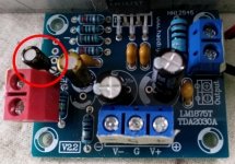
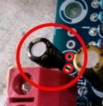
It appears from looking at the provided top and bottom views of the PCB that the pads that cap are soldered to are connected together on the bottom side of the board.
The red circles show the two pads I believe that cap should connect to.
.........yes,looks like the elcap should be shifted one position "towards
the heatsink"
- Home
- Amplifiers
- Chip Amps
- LM1875 non funziona