I suspect pin 4 is NOT connected to pin 2 through resistor **or** pin 2 is grounded.
1) turn amp OFF, wait until rails are ZERO.
If after 2 minutes you still have some residual voltage, short them to ground with a piece of wire.
2) measure resistance from pin 4 to pin 2 using the resistance scale (200k), straight from chipamp pin to pin, post result.
3) on the 2k resistance scale, measure resistance from pin 2 to ground, again straight from chipamp leg.
Post results.
EDIT: the nice schematic you posted on #98 is not too useful, since what you have is clearly different ... or it would work.
That sounds a bit to close to zero.
Pin 1 should see a very tiny voltage caused by the input bias current of the amp flowing in the input resistor. It will be very very small but non the less present. It would be around 5 millivolts or so with a 22k input resistor.
Although pin 2 should also be near zero, in the faulty state it should be following the output pin and you say you have around 14 volts there.
So you must look at why that 14 volts is not trying to pull pin 2 to that voltage. Check that your feedback resistor connect between the output pin and pin 2.
Also do a resistance check (with the amp off) between pin 2 and ground to make sure you have not got an accidental short somewhere.
I suspect pin 4 is NOT connected to pin 2 through resistor **or** pin 2 is grounded.
🙂 we think the same here I think 😉
ok tomorrow morning I will do these checks, for now thank you you are always very kind. see you tomorrow
Hello everyone, here are the measurements: pin 4 is connected to 2 through a 22k resistor measuring between 2 and 4 with power supply switched on from zero, with power supply switched off for 22k. from pin 2 to ground I give 4.7 ohm. the feedback resistor (22k) is connected between 2 and 4. between pin 2 and the ground it gives me continuity (short), but also a resistance of 4.7 with the power supply off.
Pin 2 should not read 4.7 ohm/and/or short to ground. You need to investigate that. Isolate pin 2 of the chip and remeasure from the 22k to ground.
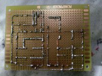
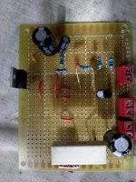

if you can, can you tell me if the feedback circuit is mounted correctly? because i doubt that i am systematically wrong.
well something is wrong, if all your components are ok then something is miswired.
as Mooly was saying the output pin measurement is way to low should be more on the order of like 10k or greater...
as Mooly was saying the output pin measurement is way to low should be more on the order of like 10k or greater...
I think I will give up, for manifest inability, it seems absurd to me that I cannot assemble such a simple circuit
don't give up! i know it frustrating but it's likely a simple oversight a slow methodical approach and the occasional pause for a shot of vino or in my case scotch should get you through it!
- Home
- Amplifiers
- Chip Amps
- LM1875 non funziona