I have tried different power supplies, now I'm using a 17 per branch, filtered and straightened, (which should be fine right?) I mounted two boards with new 1875s, one texas and one national
and the result is absolute nothing, I do not know what else to do, I used a scheme that gave me mooly, very simple, I followed all his indications
nothing to do, the chips are powered correctly the input signal is there, output as well, this thing is becoming a joke, boh
and the result is absolute nothing, I do not know what else to do, I used a scheme that gave me mooly, very simple, I followed all his indications
nothing to do, the chips are powered correctly the input signal is there, output as well, this thing is becoming a joke, boh
17!
AC or is that the final DC value... not that it matters because both would be fine.
I don't know what to suggest to you 🙂 the circuits are classic text book implementations and are built countless times successfully.
The thing now is not to give up but to progress and learn and find out why it doesn't work.
Always begin by measuring all the DC voltages around the chip, and as you know all should be zero apart from the two power pins.
You now have to look with a scope and see if the input signal is reaching the input pin correctly. Never assume anything.
The chip should be pretty much cold but you can check to see if it draws the correct quiescent current which would be around 60 to 100 milliamps per DC rail.
Leave it aside for a week and then look at ait again.
Ghosts and witches do not exist, there MUST be an error, just you don´t "see" it.
Look again 🙂
Ghosts and witches do not exist, there MUST be an error, just you don´t "see" it.
Look again 🙂
Sorry guy's don't want to step on anybodies toes, but I have used this circuit as is in a boombox, IIRC it worked 100% the first time, easy pcb to make as well.😉
Don't think you can get it more easy than that.
Don't think you can get it more easy than that.
Attachments
Last edited:
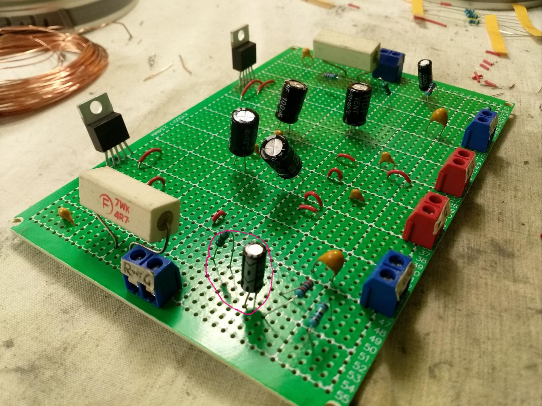
nice layout Vrystaat certainly shorter lead lengths and layout space what are the dimensions of your board?
compared to
compared to
I have tried different power supplies, now I'm using a 17 per branch, filtered and straightened, (which should be fine right?) I mounted two boards with new 1875s, one texas and one national
and the result is absolute nothing, I do not know what else to do, I used a scheme that gave me mooly, very simple, I followed all his indications
nothing to do, the chips are powered correctly the input signal is there, output as well, this thing is becoming a joke, boh
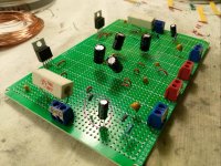
Please post pictures. The best diagnoses you received on the thread were after we were able to see what you're doing. When folks are thousands of kilometers apart, words do a very poor job of communicating.
A few pics will help us gain insight as to what has gone wrong. You say you've replaced the chips, have you got a tighter layout? Is the decoupling close? Is there a heatsink? Are the voltages okay?
We'll need more information to help you. It is okay to be frustrated, but I can't think of any one member on this forum who's not had this experience at least once. Every week.
Turk, the board is 50mm x 30mm, very small.nice layout Vrystaat certainly shorter lead lengths and layout space what are the dimensions of your board?
compared to
so 2 x1.25 inches...cool!
so i wonder if the OP has reasoned that part of his troubles could well be from instability from poor circuit layout...i learned a lot when i was trying to refine my chops with respect to RF circuits after that even audio circuits with high gain all started resembling high frequency oscillators... i guess without a scope sometimes where just guessing at what's going wrong....isn't it just a simple audio amp....should be easy, no? (no not really! sorry i'm bad at sarcasm!)
and i think mjf might be onto something!?
Last edited:
hello everyone, I came back from a little vacation, as soon as I can I will post some photos of a circuit with 1 lm1875 mono that I made before leaving in the meantime I will check it again to see if I can make it work.
i built a mono amp with lm1875, unfortunately it doesn't work if you want I show you the photos, for mooly I did these checks: the signal reaches pin1 the chip is cold pin 4 at the output gives me variable values power correctly reaches pin 3 and pin 5. I would like to check the absorption but I don't know how to do it
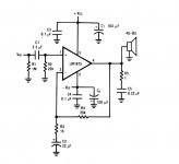
If your circuit is the standard configuration (shown attached) then pin 1 should be very close to zero volts DC. The output pin should be steady at close to zero. Pin 2 should be close to zero but will also follow the output pin.
Make sure you have the Zobel network connected at the output.
Make sure you have the Zobel network connected at the output.
Attachments
dear mooly here's what i found: pin 1 is close to zero pin 4 (output) is not zero but 14 volts pin2 is close to zero the zobel network is connected

OK 🙂
You need to do some careful measurements now. Tell me what you have here...
Measure the exact voltage on pin 1. Measure from ground and observe correct polarity, black meter lead to ground. What have you got?
Now measure pin 2 voltage exactly. What is it?
You need to do some careful measurements now. Tell me what you have here...
Measure the exact voltage on pin 1. Measure from ground and observe correct polarity, black meter lead to ground. What have you got?
Now measure pin 2 voltage exactly. What is it?
- Home
- Amplifiers
- Chip Amps
- LM1875 non funziona