mooly, can you please explain that link better that I didn't understand?
thank you
Post #38 here:
3 stage LIN topology - NFB tappings?
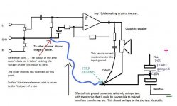
The high current speaker return must not be able to influence the inputs to the chip.
hello everyone, forgive me mooly I still haven't understood correctly: at what point of the power supply should I connect it?
You return the speaker back to the power supplies zero volt line (ground) directly and not via any of the wiring/pcb print that would allow the speakers high current to cause problems by it modulating the voltages around the chip.
Look at the diagram I linked to.
It doesn't matter how much current flows in the speaker, that current can no affect anything around the amplifier connected to the blue wire.
We have to do this because all wiring and PCB print has resistance, and that resistance develops a volt drop as current flows through it. That can cause instability and oscillation as it turns the normally negative feedback around the chip into positive feedback.
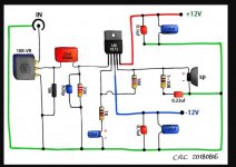
hello everyone, I reassembled a circuit with lm1875, and I always have the same problem, first a strong continuous noise to the speakers, then when I connect the source the noise disappears and the sound is heard very very distorted, I think I always make the same mistake but I can't figure out which one, it would seem a mass problem, I took pictures, if anyone wants to try to understand where I'm wrong I would thank him very much.
Pictures might help but no guarantees.
How to attach images to your posts.
When you connect the source and the noise disappears are you able to measure correct voltages on the chip?
For a dual rail supply all pins should be zero apart from the supply pins.
How to attach images to your posts.
When you connect the source and the noise disappears are you able to measure correct voltages on the chip?
For a dual rail supply all pins should be zero apart from the supply pins.
ok controllero',intanto ti mando qualche foto,sono un po disordinate penso,abbi pazienza
claudio dematteis has shared 1 photo with you! | Flickr
https://www.flickr.com/photos/189679288@N05/shares/136AU9
claudio dematteis has shared 3 photos with you! | Flickr
dimmi se riesci a vederle
An externally hosted image should be here but it was not working when we last tested it.
claudio dematteis has shared 1 photo with you! | Flickr
https://www.flickr.com/photos/189679288@N05/shares/136AU9
claudio dematteis has shared 3 photos with you! | Flickr
dimmi se riesci a vederle


Well you have done a very neat job with those boards but unfortunately it is not easy to trace out from a picture to see whether any major layout problems exist.
You must also have the chips mounted on a heatsink at all times.
Why don't you try and make just one channel work first of all. The circuit is simple enough to build 'dead bug style' without using a board. If you do this you can be certain to get the wiring correct.
You must also have the chips mounted on a heatsink at all times.
Why don't you try and make just one channel work first of all. The circuit is simple enough to build 'dead bug style' without using a board. If you do this you can be certain to get the wiring correct.
si i dissipatori li ho montati dopo, prima di provarlo,vuuoi che ti mando delle foto piu definite?ho fatto cosi ho fatto funzionare solo un canale,certo è quello che non capisco ,è cosi semplice!! si potrei usare delle pcb gia fatte ma a quel punto non c'è piu' divertimento,ma la cosa strana è che gia' le ho assemblate in passato e funzionavano correttamente,ho anche assemblato un 3886 e funzionava benissimo ,dopo un po che sono andato a riprenderlo non funzionava piu',è un mistero.
si i dissipatori li ho montati dopo, prima di provarlo,vuuoi che ti mando delle foto piu definite?ho fatto cosi ho fatto funzionare solo un canale,certo è quello che non capisco ,è cosi semplice!! si potrei usare delle pcb gia fatte ma a quel punto non c'è piu' divertimento,ma la cosa strana è che gia' le ho assemblate in passato e funzionavano correttamente,ho anche assemblato un 3886 e funzionava benissimo ,dopo un po che sono andato a riprenderlo non funzionava piu',è un mistero.
sei magnifico mooly .grazie 🙂
English please:
yes the sinks I mounted them after, before trying it, I want you to send you more definite photos?I did so I made only one channel work,certainly that's what I do not understand , it's so simple!! you could use some pcb already made but at that point there is no more fun, but the strange thing is that already I assembled them in the past and they worked properly, I also assembled a 3886 and it worked very well , after a while I went to take it it no longer worked, it's a mystery.
you're magnificent mooly, thank you
I know
 but thanks for confirming it 😉
- Home
- Amplifiers
- Chip Amps
- LM1875 non funziona